Water dispensing device, kit and method

Inactive Publication Date: 2005-12-06
ROHRER MICHAEL W
26 Cites 59 Cited by

AI-Extracted Technical Summary

Problems solved by technology

However, transportation of a pet creates peculiar circumstances that do not lend themselves to the conventional water bowl.
In addition, transportation places most pets under stress causing an increase in water consumption.
While all of the above-described devices fulfill their respective, particular objectives and requirements, the aforemen...

Benefits of technology

[0013]It is therefore an object of the present invention to provide a new and improved water dispensing device that has all the advantages of the prior art water dispensing device and none of the disadvantages.
[0014]It is another object of the present invention to provide a new and improved water dispensing device that may be easily and efficiently manufactured and marketed....

Abstract

A water dispensing device, an associated kit and a method of using same are disclosed for use in hydrating a pet such as a dog or cat. The water dispensing device includes a base unit slidably attached to a storage vessel. The base unit includes the interconnected constituents of a housing; a frame wall; and a door. The storage vessel includes the interconnected constituents of a flip top; a hollow body; and a hollow outlet port. The kit includes the unattached elements of the device. The method of using same includes the steps of adjoining, affixing, closing, grabbing, joining, letting, obtaining, opening, plugging, pouring, pushing, and releasing.

Application Domain

Technology Topic

Image

  • Water dispensing device, kit and method
  • Water dispensing device, kit and method
  • Water dispensing device, kit and method

Examples

  • Experimental program(1)

Example

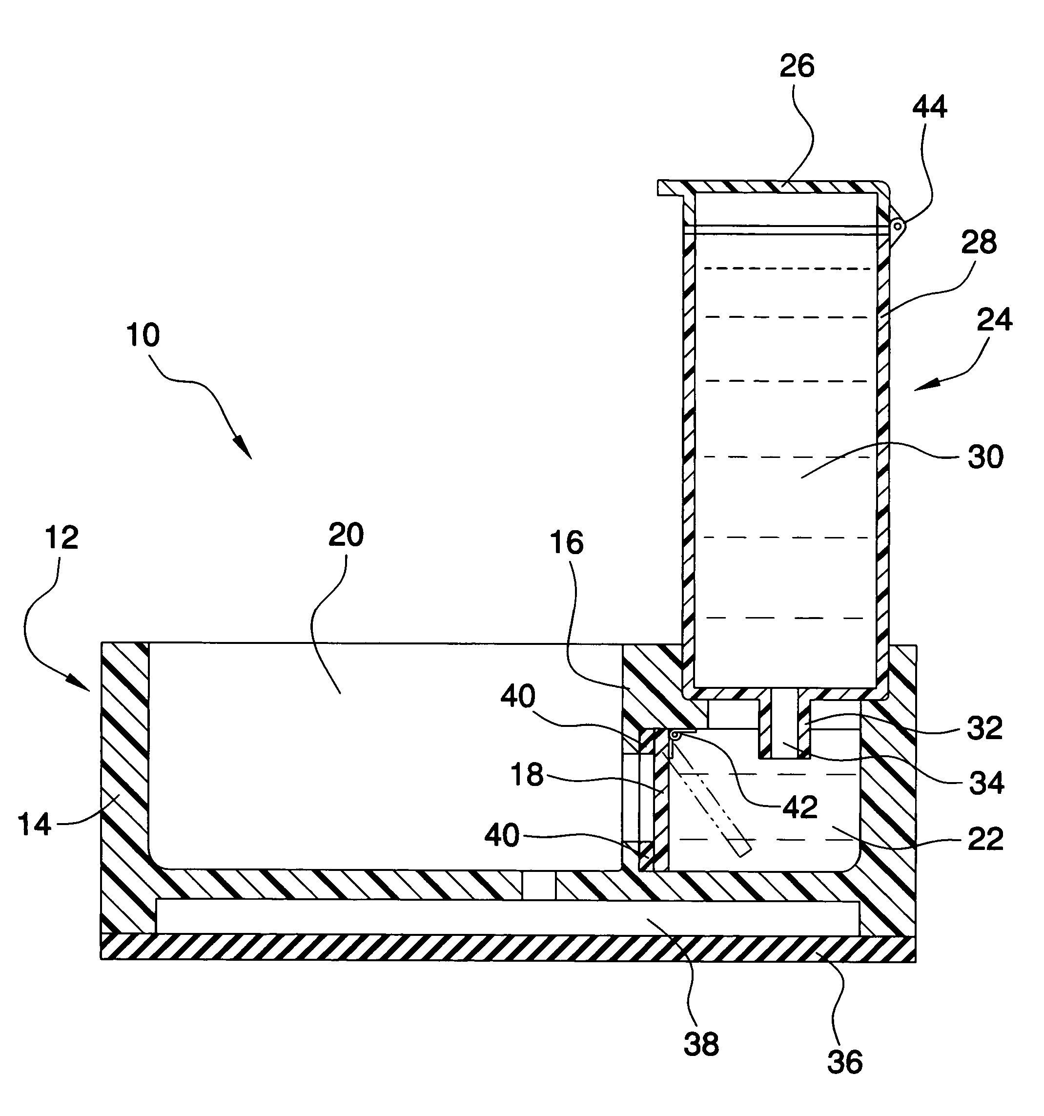
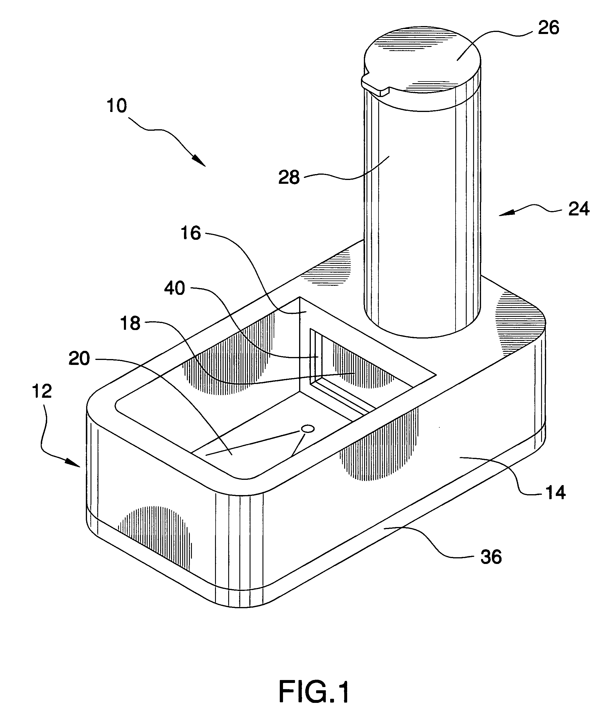
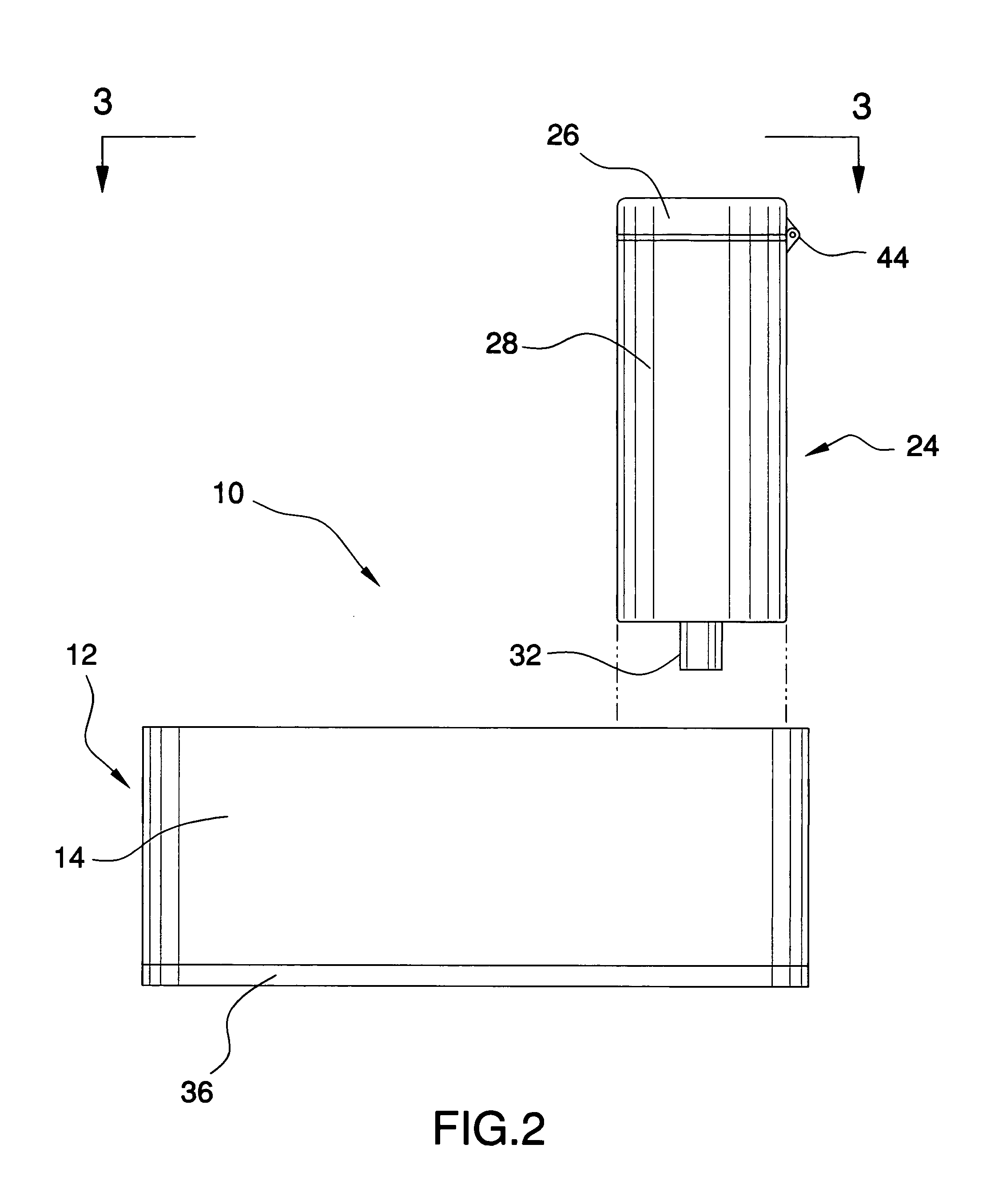
[0027]Referring now to the drawings, and in particular FIGS. 1 to 4 thereof, one preferred embodiment of the present invention is shown and generally designated by the reference numeral 10. One preferred embodiment of a water dispensing device 10 for hydrating pets, the device 10 comprises a base unit 12 slidably attached to a storage vessel 24. The base unit 12 includes a housing 14; a frame wall 16; and a door 18. The frame wall 16 is attached to the housing 14. The door 18 is pivotally attached to the frame wall 16, wherein the door 18, the frame wall 16, and the housing 14 defining an open reservoir 20 and a closed reservoir 22. When the door 18 is pivoted away from the frame wall 16 then the open reservoir 20 is in fluid communications with the closed reservoir 22. When the door 18 is pivoted towards then the frame wall 16 the open reservoir 20 is not in fluid communications with the closed reservoir 22. The storage vessel 24 includes: a flip top 26; a hollow body 28; and a hollow outlet port 32. The hollow body 28 is pivotally attached to the flip top 26, the hollow body 28 also has a holding reservoir 30. The hollow outlet port 32 is attached to the hollow body 28, in which the hollow outlet port 32 has an internal fluid passage 34 in fluid communications with the holding reservoir 30 of the hollow body 28. When the storage vessel 24 is slidably attached to the base unit 12 then the holding reservoir 30 is in fluid communications with the closed reservoir 22.
[0028]An optional pad 36 may be added to the device 10 in which the optional pad 36 is attached to the housing 14. The pad 36 may be made of any commercially available material. One preferred configuration is that the pad 36 is made of plastic selected from the group consisting of rubber, neoprene, nylon, polyvinyl chloride, polyester, polyethylene, polypropylene, polyurethanes, polyacryls, polymethacryls, cellulosic polymers, styrene-acryl copolymers, polystyrene-polyacryl mixtures, polysiloxanes, urethane-acryl copolymers, siloxane-urethane copolymers, polyurethane-polymethacryl mixtures, silicone-acryl copolymers, vinyl acetate polymers, and mixtures thereof.
[0029]An optional counterweight 38 may be added to the device 10 in which the optional counterweight 38 is attached to the pad 36 and attached to the housing 14. The counterweight 38 may be made of any commercially available material. One preferred configuration is that the counterweight 38 is made of metal selected from the group consisting of lead, copper, iron, steel, stainless steel, manganese, magnesium, vanadium, nickel, tungsten, and molybdenum.
[0030]An optional gasket 40 may be added to the device 10 in which the optional gasket 40 is attached to the frame wall 16. The gasket 40 may be made of any commercially available material. One preferred configuration is that the gasket 40 is made of plastic selected from the group consisting of rubber, neoprene, nylon, polyvinyl chloride, polyester, polyethylene, polypropylene, polyurethanes, polyacryls, polymethacryls, cellulosic polymers, styrene-acryl copolymers, polystyrene-polyacryl mixtures, polysiloxanes, urethane-acryl copolymers, siloxane-urethane copolymers, polyurethane-polymethacryl mixtures, silicone-acryl copolymers, vinyl acetate polymers, and mixtures thereof.
[0031]An optional spring hinge 42 may be added to the device in which the optional spring hinge 42 is attached to the frame wall 16 and attached to the door 18.
[0032]An optional angle hinge 44 may be added to the device in which the optional angle hinge 44 is attached to the flip top 26 of the storage vessel 24 and attached to the hollow body 28 of the storage vessel 24.
[0033]The housing 14 may be made of any commercially available material such as plastic selected from the group consisting of rubber, neoprene, nylon, polyvinyl chloride, polyester, polyethylene, polypropylene, polyurethanes, polyacryls, polymethacryls, cellulosic polymers, styrene-acryl copolymers, polystyrene-polyacryl mixtures, polysiloxanes, urethane-acryl copolymers, siloxane-urethane copolymers, polyurethane-polymethacryl mixtures, silicone-acryl copolymers, vinyl acetate polymers, and mixtures thereof.
[0034]The storage vessel 24 may be made of any commercially available material such as plastic selected from the group consisting of rubber, neoprene, nylon, polyvinyl chloride, polyester, polyethylene, polypropylene, polyurethanes, polyacryls, polymethacryls, cellulosic polymers, styrene-acryl copolymers, polystyrene-polyacryl mixtures, polysiloxanes, urethane-acryl copolymers, siloxane-urethane copolymers, polyurethane-polymethacryl mixtures, silicone-acryl copolymers, vinyl acetate polymers, and mixtures thereof.
[0035]The base unit 12 may be made of any commercially available material such as plastic selected from the group consisting of rubber, neoprene, nylon, polyvinyl chloride, polyester, polyethylene, polypropylene, polyurethanes, polyacryls, polymethacryls, cellulosic polymers, styrene-acryl copolymers, polystyrene-polyacryl mixtures, polysiloxanes, urethane-acryl copolymers, siloxane-urethane copolymers, polyurethane-polymethacryl mixtures, silicone-acryl copolymers, vinyl acetate polymers, and mixtures thereof.
[0036]One preferred embodiment of a kit for a water dispensing device 10, the kit comprising: a base unit 12 and a storage vessel 24. The base unit 12 including: a housing 14; a frame wall 16 attached to the housing 14; and a door 18 pivotally attached to the frame wall 16, wherein the door 18, the frame wall 16, and the housing 14 defining an open reservoir 20 and a closed reservoir 22, when the door 18 is pivoted away from the frame wall 16 then the open reservoir 20 is in fluid communications with the closed reservoir 22, when the door 18 is pivoted towards then the frame wall 16 the open reservoir 20 is not in fluid communications with the closed reservoir 22; and a storage vessel 24 slidably attachable to the base unit 12. The storage vessel 24 including: a flip top 26; a hollow body 28 pivotally attached to the flip top 26, the hollow body 28 having a holding reservoir 30; and a hollow outlet port 32 attached to the hollow body 28, the hollow outlet port 32 having an internal fluid passage 34 in fluid communications with the holding reservoir 30 of the hollow body 28, wherein when the storage vessel 24 is slidably attached to the base unit 12 then the holding reservoir 30 is in fluid communications with the closed reservoir 22.
[0037]An optional a pad 36 attachable to the housing 14 may be added to the kit.
[0038]An optional counterweight 38 attachable to the base unit 12 may be added to the kit.
[0039]An optional gasket 40 attachable to the frame wall 16 may be added to the kit.
[0040]One preferred embodiment of a method of using a kit for assembling and utilizing a water dispensing device 10, the method comprising the steps of: adjoining, affixing, closing, grabbing, joining, letting, obtaining, opening, plugging, pouring, pushing, and releasing. The obtaining step comprises obtaining the kit comprising: a base unit 12 including: a housing 14; a frame wall 16 attached to the housing 14; a door 18 pivotally attached to the frame wall 16, wherein the door 18, the frame wall 16, and the housing 14 defining an open reservoir 20 and a closed reservoir 22, when the door 18 is pivoted away from the frame wall 16 then the open reservoir 20 is in fluid communications with the closed reservoir 22, when the door 18 is pivoted towards then the frame wall 16 the open reservoir 20 is not in fluid communications with the closed reservoir 22; a storage vessel 24 slidably attachable to the base unit 12, the storage vessel 24 including: a flip top 26; a hollow body 28 pivotally attached to the flip top 26, the hollow body 28 having a holding reservoir 30; and a hollow outlet port 32 attached to the hollow body 28, the hollow outlet port 32 having an internal fluid passage 34 in fluid communications with the holding reservoir 30 of the hollow body 28, wherein when the storage vessel 24 is slidably attached to the base unit 12 then the holding reservoir 30 is in fluid communications with the closed reservoir 22 a pad 36 attachable to the housing 14; a counterweight 38 attachable to the pad 36 and attachable to the base unit 12; and a gasket 40 attachable to the frame wall 16. The adjoining step comprises adjoining the counterweight 38 to the base unit 12. The affixing step comprises affixing the pad 36 to the counterweight 38 and to the base unit 12. The grabbing step comprises grabbing hold of the storage vessel 24. The opening step comprises opening pivotally the flip top 26 from the hollow body 28 of the storage vessel 24. The plugging step comprises plugging the hollow outlet port 32 with a finger. The pouring step comprises pouring water into the hollow body 28 of the storage vessel 24 while the flip top 26 is pivoted open and while the hollow outlet port 32 is plugged. The closing step comprises closing pivotally the flip top 26 around the hollow body 28 of the storage vessel 24 while the hollow outlet port 32 is plugged. The releasing step comprises releasing the finger from the hollow outlet port 32. The joining step comprises joining slidably together the storage vessel 24 to the base unit 12, whereby the holding reservoir 30 of the hollow body 28 is in fluid communications with the closed reservoir 22. The pushing step comprises pushing pivotally the door 18 with the finger when the storage vessel 24 is slidably joined together with the base unit 12, whereby the open reservoir 20 is in fluid communications with the closed reservoir 22. The letting step comprises letting go of the door 18 with the finger when the storage vessel 24 is slidably joined together with the base unit 12 whereby the open reservoir 20 is not in fluid communications with the closed reservoir 22.
[0041]As to the manner of usage and operation of the present invention, the same should be apparent from the above description. Accordingly, no further discussion relating to the manner of usage and operation will be provided.
[0042]While a preferred embodiment of the water dispensing device has been described in detail, it should be apparent that modifications and variations thereto are possible, all of which fall within the true spirit and scope of the invention. With respect to the above description then, it is to be realized that the optimum dimensional relationships for the parts of the invention, to include variations in size, materials, shape, form, function and manner of operation, assembly and use, are deemed readily apparent and obvious to one skilled in the art, and all equivalent relationships to those illustrated in the drawings and described in the specification are intended to be encompassed by the present invention.
[0043]Throughout this specification, unless the context requires otherwise, the word “comprise” or variations such as “comprises” or “comprising” or the term “includes” or variations, thereof, or the term “having” or variations, thereof will be understood to imply the inclusion of a stated element or integer or group of elements or integers but not the exclusion of any other element or integer or group of elements or integers. In this regard, in construing the claim scope, an embodiment where one or more features is added to any of the claims is to be regarded as within the scope of the invention given that the essential features of the invention as claimed are included in such an embodiment.
[0044]Those skilled in the art will appreciate that the invention described herein is susceptible to variations and modifications other than those specifically described. It is to be understood that the invention includes all such variations and modifications which fall within its spirit and scope. The invention also includes all of the steps, features, compositions and compounds referred to or indicated in this specification, individually or collectively, and any and all combinations of any two or more of said steps or features.
[0045]Therefore, the foregoing is considered as illustrative only of the principles of the invention. Further, since numerous modifications and changes will readily occur to those skilled in the art, it is not desired to limit the invention to the exact construction and operation shown and described, and accordingly, all suitable modifications and equivalents may be resorted to, falling within the scope of the invention.

PUM

no PUM

Description & Claims & Application Information

We can also present the details of the Description, Claims and Application information to help users get a comprehensive understanding of the technical details of the patent, such as background art, summary of invention, brief description of drawings, description of embodiments, and other original content. On the other hand, users can also determine the specific scope of protection of the technology through the list of claims; as well as understand the changes in the life cycle of the technology with the presentation of the patent timeline. Login to view more.

Similar technology patents

Classification and recommendation of technical efficacy words

  • Easily and efficiently manufacture and market
  • Low manufacturing cost

Exercise equipment

InactiveUS6942605B1Low manufacturing costLow price of saleStraight-bar knitting machinesFootwearExercise equipmentPhysical medicine and rehabilitation
Owner:SUKHOVITSKY FELIKS

Hybrid aerial and terrestrial vehicle

ActiveUS20140131507A1Simple designLow manufacturing costConvertible aircraftsMicro-sized aircraftFlight vehicleTerrestrial locomotion
Owner:ILLINOIS INSTITUTE OF TECHNOLOGY

A ceramic insulator device for high voltage capacitor

InactiveCN101546636ALow manufacturing costReasonable structureSuspension/strain insulatorsHigh voltage capacitorsEngineering
Owner:王海龙
Why Eureka
Try Eureka