Staple extractor structure

a staple extractor and structure technology, applied in the field of staple extractor structure, can solve the problems of slow practical use and inconvenience of the conventional staple extractor, and achieve the effect of improving the structure of the staple extractor and convenient application

Inactive Publication Date: 2005-12-06
WELTERS
View PDF4 Cites 0 Cited by
  • Summary
  • Abstract
  • Description
  • Claims
  • Application Information

AI Technical Summary

Benefits of technology

[0004]It is, therefore, the primary purpose of the present invention to provide an improved staple extractor structure, including a movable member, a guide pressing board, a spring element, and an engaging piece wherein, via the design of the movable member and the guide pressing board, the staple extractor of the present invention can be directly and levelly placed on top of paper to remove staples pinned on the paper without hands holding on thereto, facilitating an easier and convenient application and achieving the best using condition of the present invention.

Problems solved by technology

There are some drawbacks to the conventional staple extractor above.
Thus, the conventional staple extractor thereof is rather inconvenient and slow in practical use.

Method used


Image

  • Staple extractor structure
  • Staple extractor structure
  • Staple extractor structure

Examples


Embodiment Construction

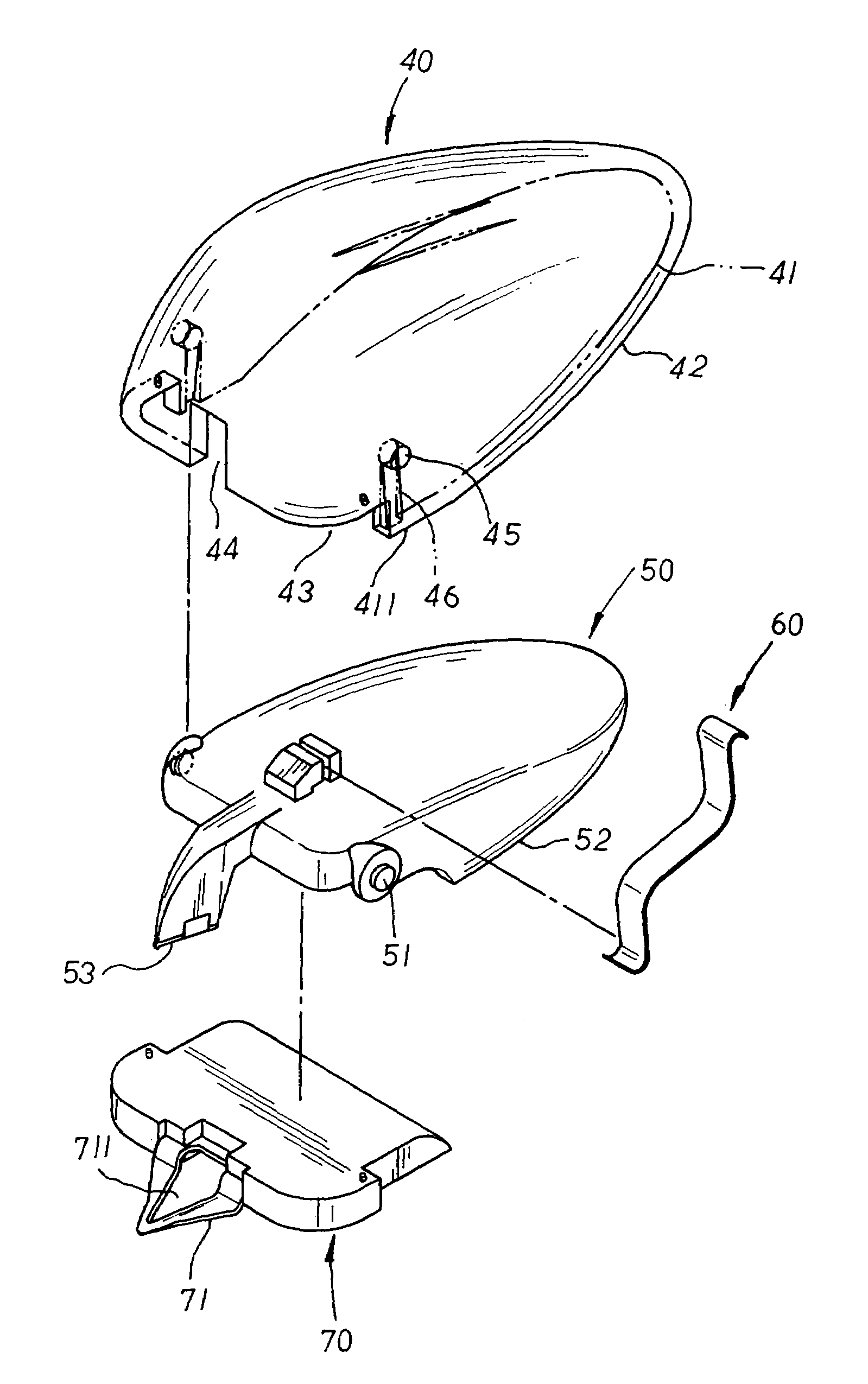
[0010]Please refer to FIG. 3. The present invention is related to an improved staple extractor structure, including a movable member 40 made up of an engaging cavity 41 concaved upwards at the underside therein, an upwardly-tilting engaging edge 42 properly cut at one side of the opening of the engaging cavity 41 thereof, a U-shaped coupling recess 43 extending from edge to edge at the front bottom side thereon, and a central limiting groove 44 properly indented upwards at the front side of the coupling recess 43 thereof. At preset positions on the inner wall of the engaging cavity 41 thereof is symmetrically disposed a pair of pivoting holes 45 each communicating with a vertical guide track 46 extending downwards at the bottom side thereof. A guide pressing board 50 is provided with a pair of symmetrical pivoting rods 51 to be led upwards via the vertical guide tracks 46 till precisely registered with the pivoting holes 45 for locating the guide pressing board 50 at the engaging ca...


PUM


Abstract

An improved staple extractor structure includes a movable member having an upwardly-tilting engaging edge properly cut at one side of an engaging cavity concaved upwards at the underside therein, and a U-shaped coupling recess disposed at the front bottom side thereof for retaining an engaging piece with a flat puller fixedly attached thereto. A central limiting groove is properly indented upwards at the front side of the coupling recess thereof, and at preset positions on the inner wall of the engaging cavity thereof is symmetrically disposed a pair of pivoting holes to be mutually registered with pivoting rods of a guide pressing board permitting a push block of the guide pressing board to be precisely located at the limiting groove therein and protruding outwards there-from in match to the flat puller thereof A spring element is respectively attached at the inner wall of the engaging cavity.

Description

BACKGROUND OF THE INVENTION[0001]The present invention is related to an improved staple extractor structure, including a movable member having an engaging cavity concaved upwards at the underside therein, and a U-shaped coupling recess disposed at the front bottom side thereof for retaining an engaging piece with a flat puller fixedly attached thereto. At preset positions on the inner wall of the engaging cavity thereof is symmetrically disposed a pair of pivoting holes to be mutually registered with pivoting rods of a guide pressing board having a protrusive push block extending at the front side thereof in match to the flat puller of the engaging piece thereof. A spring element is respectively attached at the inner wall of the engaging cavity and the upper surface of the guide pressing board by both ends thereof, permitting the rear side of the movable member to be elastically supported upwards thereby; thus, via the design of the movable member and the guide pressing board, the s...

Claims


Application Information

Patent Timeline
Patent Type & Authority Patents(United States)
IPC IPC(8): B25C11/00
CPCB25C11/00
Inventor HSU, WALTER
Owner WELTERS
Why Eureka
Try Eureka