Milling tool holder with differential screw

a technology of differential screw and tool holder, which is applied in the directions of attachable milling device, manufacturing tools, transportation and packaging, etc., can solve the problem of poor finishing of workpieces

Inactive Publication Date: 2005-12-06
STOJANOVSKI STOJAN
View PDF11 Cites 14 Cited by
  • Summary
  • Abstract
  • Description
  • Claims
  • Application Information

AI Technical Summary

Problems solved by technology

However, most commonly used apparatus still tend to permit the tool to chatter from the tool movement such as when using a hydraulic pull system with a retention hub.
Further such apparatus sometimes permit tool deflection which results in a poorly finished workpiece.

Method used


Image

  • Milling tool holder with differential screw
  • Milling tool holder with differential screw
  • Milling tool holder with differential screw

Examples


Embodiment Construction

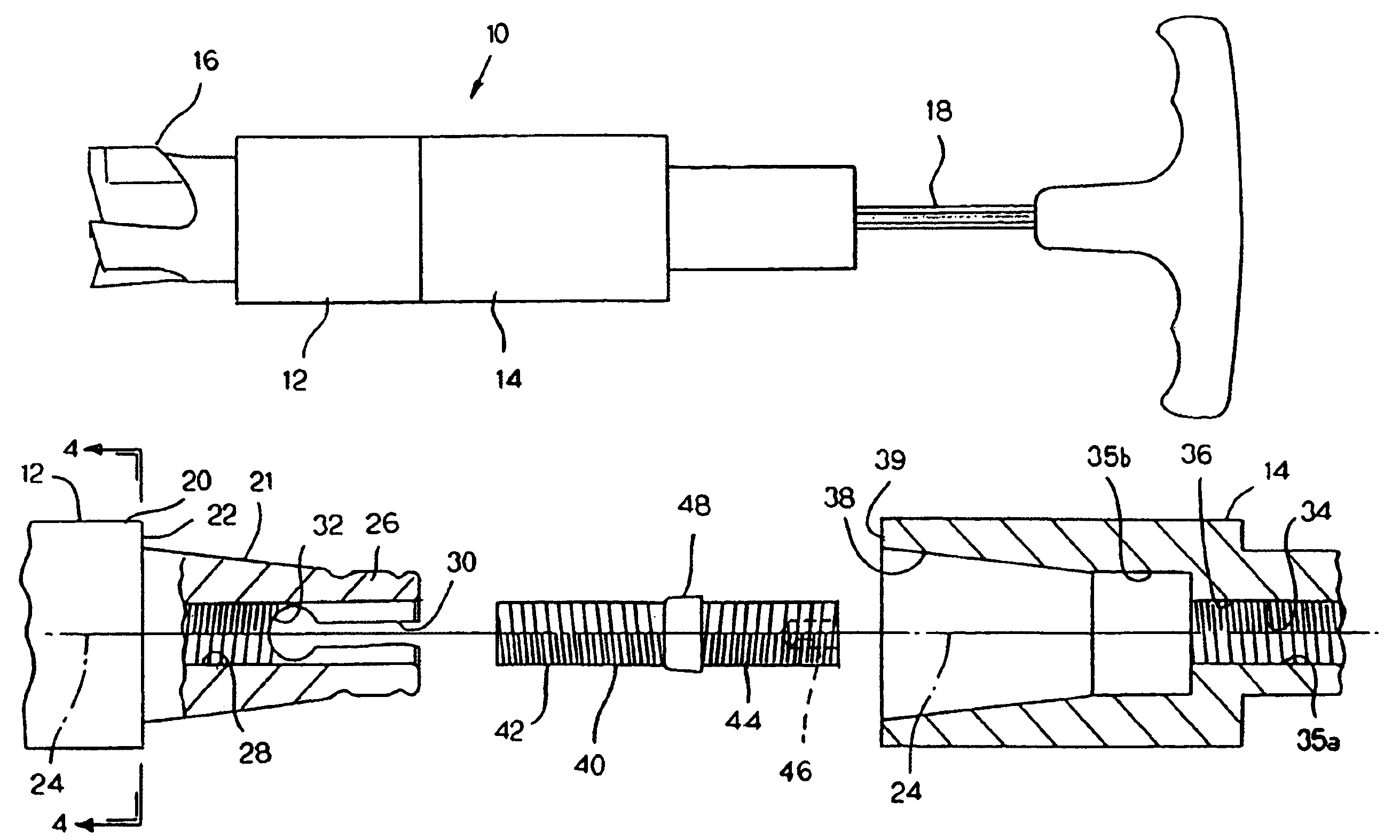
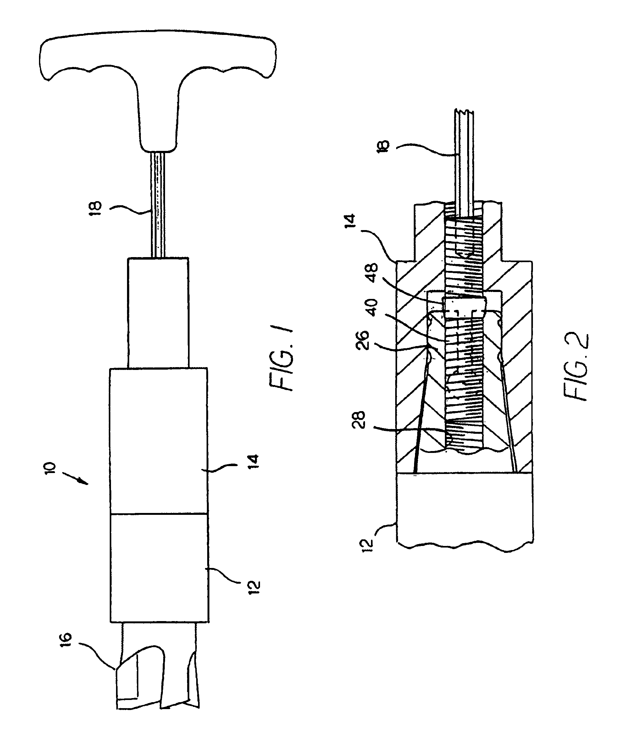
[0014]Referring to the drawings, FIG. 1 illustrates a preferred tool holder combination 10 which comprises a tool holder 12 joined to a spindle 14. A milling tool 16 is an integral element of the tool holder. An elongated hexagonal wrench 18 is illustrated mounted inside the spindle for purposes which will be described. The spindle is adapted to be driven by a rotating drive means, not shown.

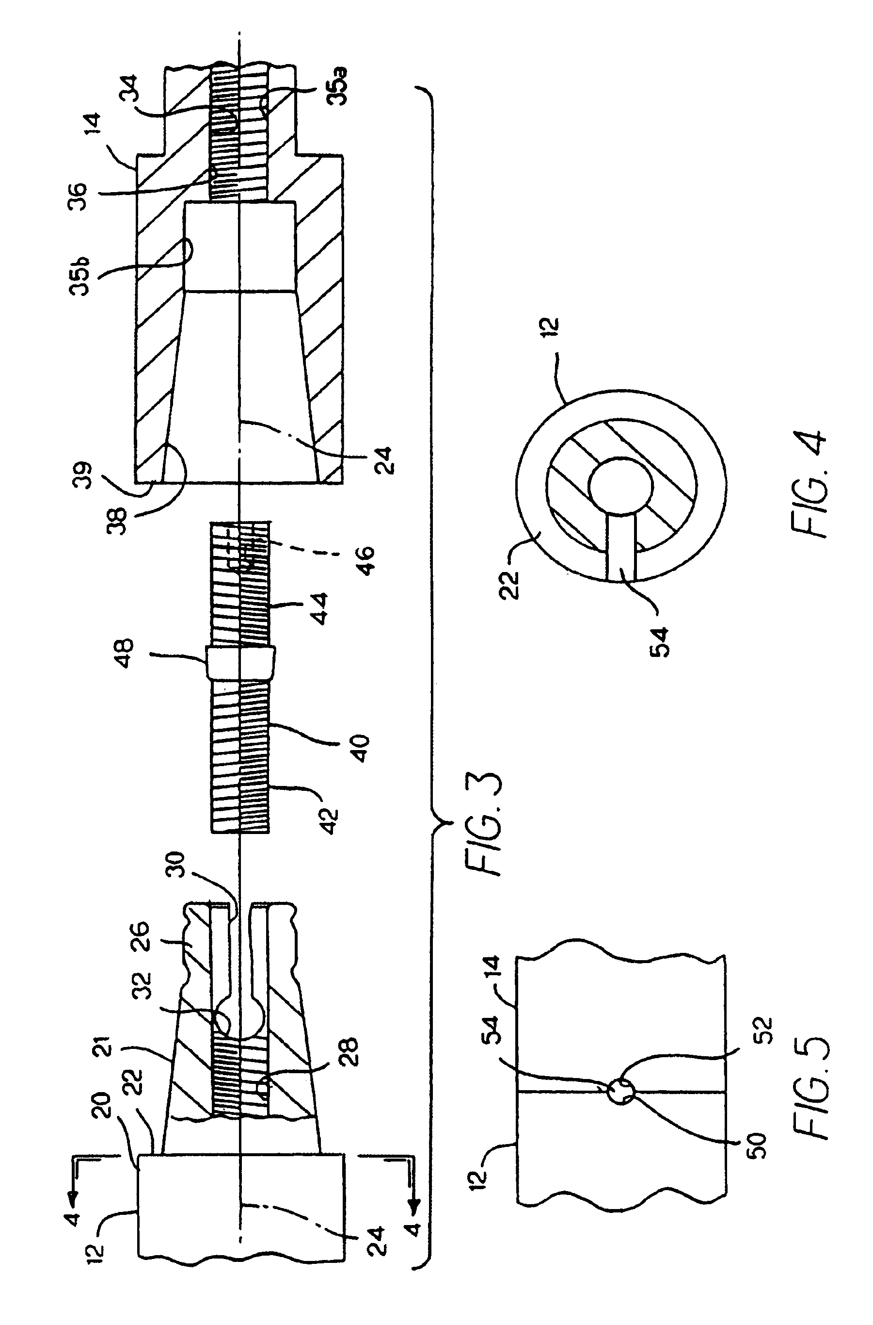
[0015]Referring to FIG. 2, tool holder 12 comprises a body 20. A tapered shank 21 forms an integral part of the inner end of the tool holder body with the wide end of the shank terminating in an annular seat 22. In use, the shank and the tool holder body rotates about an axis of rotation 24.

[0016]The tapered shank terminates in a collar 26. The shank has an internal threaded bore 28, and a smooth bore in the collar. A pair of axial running slot means 30 are formed in the collar in such a manner that the two halves of the collar can be expanded from their normal position illustrated in FIG. 3. Ea...


PUM

PropertyMeasurementUnit
pressureaaaaaaaaaa
diameteraaaaaaaaaa
widthaaaaaaaaaa

Abstract

A milling tool holder having a spindle with a tapered opening and a tool holder having a tapered shank that fits into the spindle opening. The narrow end of the shank has a split collar. The spindle is joined to the tool holder by inserting the shank into the tapered opening and drawing the two components together using a differential screw. When the differential screw is turned in one direction, the two components are drawn together, and when turned in the opposite direction, the two components are separated. As the shank bottoms in the tapered opening, an annular enlargement on the differential screw expands the split collar of the shank to tightly seat the shank in the spindle.

Description

BACKGROUND OF THE INVENTIONBACKGROUND AND SUMMARY OF THE INVENTION[0001]Tool holders for milling tools commonly employ a tool holding component having a shank, and a driven spindle having an opening for receiving the shank. Various ways are known in the prior art for tightly joining the spindle to the shank of the tool holder. However, most commonly used apparatus still tend to permit the tool to chatter from the tool movement such as when using a hydraulic pull system with a retention hub. Further such apparatus sometimes permit tool deflection which results in a poorly finished workpiece.[0002]The broad purpose of the present invention is to provide an improved tool holder combination comprising an elongated tool holder having a threaded bore, one end for supporting a milling tool and its opposite end having a tapered shank. The wide end of the shank merges with an annular seat on the tool holder. The narrow end of the shank merges with a generally cylindrical split collar having ...

Claims


Application Information

Patent Timeline
Patent Type & Authority Patents(United States)
IPC IPC(8): B23B31/11B23C1/00B23C5/00B23C5/10B23C5/26
CPCB23B31/1107B23B31/1122B23C5/10Y10T409/309464Y10T279/16Y10T409/309408Y10T408/957B23C2210/03
Inventor STOJANOVSKI, STOJAN
Owner STOJANOVSKI STOJAN
Why Eureka
Try Eureka