
Telescopic differential screw mechanism based 3-dof-parallel manipulator platform to achieve omnidirectional bending

a technology of differential screw and manipulator platform, which is applied in the direction of manipulator, programmed manipulator, and manufacture of tools, can solve the problems of increasing the material cost of production, increasing the length of the actuator or the screw or the nuts, so as to facilitate the actuation of compliant high traction surface, high traction, and enhance the effect of capabilities

Active Publication Date: 2019-08-01
INT INST OF INFORMATION THCHNOLOGY HYDERABAD
View PDF0 Cites 5 Cited by
  • Summary
  • Abstract
  • Description
  • Claims
  • Application Information

AI Technical Summary

Benefits of technology

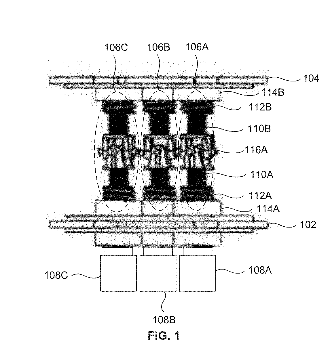
The patent text describes a versatile robot module that can move in different directions and has a compliant surface for better traction. It includes three telescopic screw assemblies that can bend in the same direction, which allows the robot to move smoothly and with reduced friction. The module also includes a driving actuator and a module that can move vertically or longitudinally, providing high traction on both surfaces. The robot uses a telescopic 3-DOF parallel manipulator system to change the length of its chassis and achieve omnidirectional bending. This allows it to move in tight spaces and perform high traction motion in both vertical and lateral directions.

Problems solved by technology

The disadvantages with this type of actuators for achieving omnidirectional bending is that in order to increase the desired bending angle, the length of the actuators increases proportionally.
The increase in length of the actuators or screws or nuts increases the material cost for production.
Also, these types of actuators that are used for achieving omnidirectional bending require high maintenance cost and high production cost.
Also, challenges like large turning radius, restrict its maneuverability in tight spaces.
The misalignment in single actuator of the existing approaches may collapse the entire functioning.

Method used


Image

  • Telescopic differential screw mechanism based 3-dof-parallel manipulator platform to achieve omnidirectional bending
  • Telescopic differential screw mechanism based 3-dof-parallel manipulator platform to achieve omnidirectional bending
  • Telescopic differential screw mechanism based 3-dof-parallel manipulator platform to achieve omnidirectional bending

Examples


Embodiment Construction

[0034]The embodiments herein and the various features and advantageous details thereof are explained more fully with reference to the non-limiting embodiments that are illustrated in the accompanying drawings and detailed in the following description. Descriptions of well-known components and processing techniques are omitted so as to not unnecessarily obscure the embodiments herein. The examples used herein are intended merely to facilitate an understanding of ways in which the embodiments herein may be practiced and to further enable those of skill in the art to practice the embodiments herein. Accordingly, the examples should not be construed as limiting the scope of the embodiments herein.

[0035]As mentioned, there remains a need for a compact and cost-effective mechanism to achieve omnidirectional bending. The embodiments herein achieve this by providing a telescopic screw mechanism based 3-DOF Parallel Manipulator system for achieving omnidirectional bending. Referring now to t...


PUM


Abstract

A telescopic differential screw mechanism based 3-DOF Parallel Manipulator system to enable differential length and omnidirectional bending is provided. The telescopic differential screw mechanism based 3-DOF Parallel Manipulator system includes a first circular rotating plate 102, a second circular rotating plate 104, three or more telescopic screw assemblies 106A-C and three or more actuators 108A-C. Each telescopic screw assembly 106 includes a pair of master screws 110, a pair of successive screws 112 and a universal joint 116. The three or more telescopic screw assemblies 106A-C are actuated differentially using the three or more actuators 108A-C to achieve omnidirectional bending with high angular rotations in a range of 0 to 75 degree.

Description

BACKGROUNDTechnical Field[0001]The embodiments herein generally relate to omnidirectional bending, and more particularly, to a telescopic differential screw mechanism based three degree of freedom parallel manipulator system to achieve omnidirectional bending.Description of the Related Art[0002]Existing approaches for achieving omnidirectional bending is done using prismatic actuators, electric actuators or hydraulic actuators based on three degree of freedom (3-DOF) Parallel Manipulator system. The disadvantages with this type of actuators for achieving omnidirectional bending is that in order to increase the desired bending angle, the length of the actuators increases proportionally. The increase in length of the actuators or screws or nuts increases the material cost for production. Also, these types of actuators that are used for achieving omnidirectional bending require high maintenance cost and high production cost. Though, certain compliant snake robot structures have advanta...

Claims


Application Information

Patent Timeline
Patent Type & Authority Applications(United States)
IPC IPC(8): F16H25/20B25J17/00B25J18/02
CPCF16H25/2056F16H25/2015B25J17/00B25J18/025B25J9/003
Inventor KRISHNA, MADHAVASINGH, AKASHSACHDEVA, ENNARODRIGUES, VINAY
Owner INT INST OF INFORMATION THCHNOLOGY HYDERABAD
Learn More