
Mechanism for enhanced, bi-directional fine adjustment of cutting insert cartridges in machine tools

A technology for cutting inserts and machining tools, used in cutting inserts, tools for lathes, accessories for tool holders, etc., which can solve problems such as loss of productivity and operational efficiency, loss of time, etc.

Active Publication Date: 2016-04-06
SANDVIK INTELLECTUAL PROPERTY AB
View PDF8 Cites 5 Cited by
  • Summary
  • Abstract
  • Description
  • Claims
  • Application Information

AI Technical Summary

Problems solved by technology

This repetitive positioning creates a loss of time as well as a loss of productivity and operational efficiency

Method used


Image

  • Mechanism for enhanced, bi-directional fine adjustment of cutting insert cartridges in machine tools
  • Mechanism for enhanced, bi-directional fine adjustment of cutting insert cartridges in machine tools
  • Mechanism for enhanced, bi-directional fine adjustment of cutting insert cartridges in machine tools

Examples


Embodiment Construction

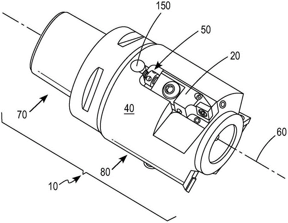
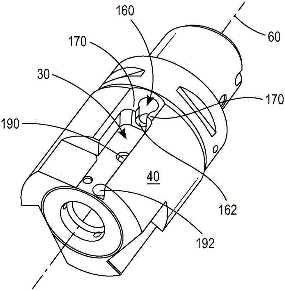
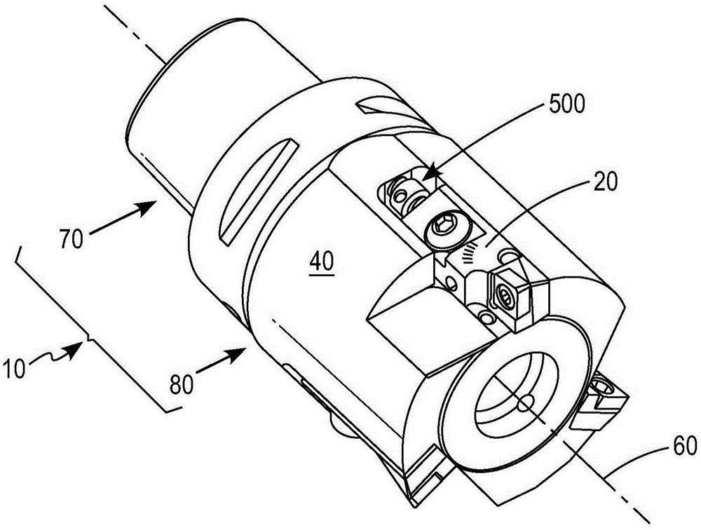
[0022] figure 1 is a perspective view of an exemplary embodiment of a chip removal machining tool with a cutting insert cartridge and a first exemplary embodiment of an axial adjustment system including a differential screw, and figure 2 is a perspective view of another exemplary embodiment of a chip removal machining tool with a cutting insert cartridge and a second exemplary embodiment of an axial adjustment system including a differential screw. Exemplary chip removal machining tools 10 each include a cutting insert cartridge 20 mounted in a slot 30 (or other receiving area) in a surface of a tool body 40 . Axial adjustment system ( figure 1 The first exemplary axial adjustment system 50 in; figure 2 The second exemplary axial adjustment system 500 in ) axially translates the cutting insert cartridge 20 in the slot relative to the longitudinal axis 60 of the tool body 40 . figure 1 with figure 2 Other features of the cutter body shown in include an attachment end por...


PUM


Abstract

The present invention relates to a mechanism for enhanced, bi-directional fine adjustment of cutting insert cartridges in machine tools. A cutting insert cartridge for chip removing machining tools has an axial adjustment system threadedly engaged with a cartridge body and a tool body. The axial adjustment system includes a differential screw in threaded engagement with the tool body either directly, for example by threaded engagement with a threaded openingin the tool body, or indirectly, for example by threaded engagement with a cross dowel fastener slidably positioned in an opening in the tool body. Actuation portion positioned axially between threaded end portions of the differential screw has an engagement feature on an outer surface to be driven, e.g., with a tool or by hand, to rotate the differential screw and adjust the axial position of the cartridge. The spaced apart relationship improves access to the actuation portion and engagement feature for rotation of the differential screw. Chip removing machining tools with such cartridges, methods of adjusting the position of the cartridge and cutting insert adjustment differential screws are also disclosed.

Description

technical field [0001] The present disclosure relates to chip removal machining tools for cutting workpieces. More specifically, the present disclosure relates to a mechanism for bi-directionally adjusting the position of a cutting insert cartridge relative to the body of a chip removal machining tool using a differential adjustment screw having opposed threaded ends at a first The ends interact with the threaded formation and at the second end with the threaded portion of the cartridge, and an actuation portion having an engagement feature on the outer surface is interposed between the threaded ends. The present disclosure relates to toolholders and adjustment mechanisms, as well as chip removal tool and toolholder combinations, and differential adjustment screws themselves. Background technique [0002] In the following discussion, reference is made to certain structures and / or methods. However, the following references should not be construed as an admission that these ...

Claims


Application Information

Patent Timeline
Patent Type & Authority Applications(China)
IPC IPC(8): B23B27/16
CPCB23B27/1685B23B2205/04B23B29/0341B23B2260/056B23C2260/28B23C5/2472B23C5/24B23C5/2226B23B29/00B23C5/2479B23C5/2278
Inventor 叶夫根尼·科切罗夫斯基
Owner SANDVIK INTELLECTUAL PROPERTY AB
Learn More