Thermal error differential screw compensating device and using method thereof

A technology of compensation device and differential screw, which is applied in other manufacturing equipment/tools, manufacturing tools, etc., can solve the problem of poor robustness and versatility of the compensation control system, error compensation value cannot be inserted in real time, and does not have real-time error compensation function and other problems to achieve the effect of good versatility, smooth movement and simple structure

Active Publication Date: 2010-08-04
CHONGQING UNIV +1
View PDF0 Cites 6 Cited by
  • Summary
  • Abstract
  • Description
  • Claims
  • Application Information

AI Technical Summary

Problems solved by technology

[0006] Another method to reduce the influence of thermal deformation is thermal error compensation technology, which uses various detection methods to directly or indirectly measure the errors generated during CNC machining, and then performs error compensation calculations based on the established error compensation model. Feedback the calculation results to the CNC system, so that the controller can issue corresponding control error compensation instructions to compensate the corresponding thermal errors and eliminate the influence of thermal deformation. This method is the main means to eliminate thermal deformation of machine tools and improve its machining accuracy, but most CNC The openness of the system is not enough, and the error compensation value calculated by the error model cannot be inserted into the generated NC program in real time, that is, real-time error compensation cannot be realized
In addition, most CNC systems themselves do not have real-time error compensation functions, so when performing compensation tasks, it is necessary to design interface circuits specifically for specific machine tools
Moreover, most of the current research conducted by the institute is some case studies, which are aimed at some special machine tools, and the proposed compensation control system has poor robustness and versatility.

Method used


Image

  • Thermal error differential screw compensating device and using method thereof
  • Thermal error differential screw compensating device and using method thereof
  • Thermal error differential screw compensating device and using method thereof

Examples


Embodiment Construction

[0021] The present invention will be further described below in conjunction with the accompanying drawings and embodiments.

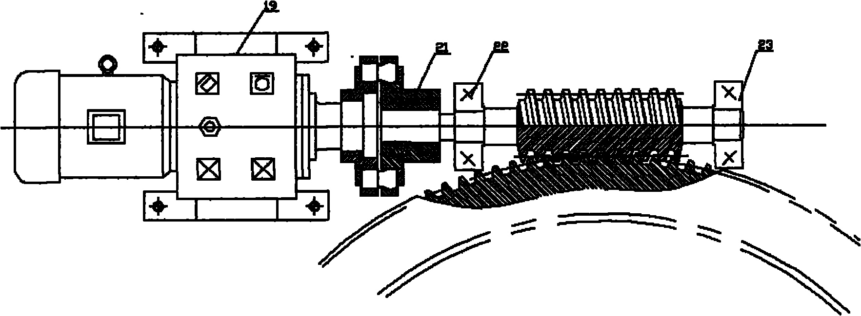
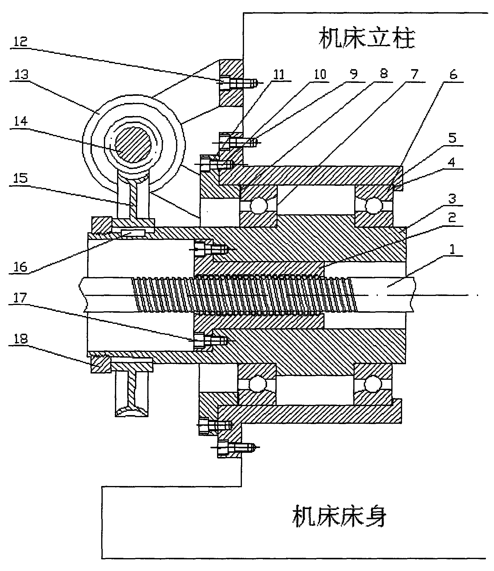
[0022] like figure 1 As shown, a thermal error differential screw compensation device provided by the present invention includes a screw nut transmission system, a worm gear compensation system, a sleeve, a support bearing, a washer, and the like. During the assembly process, the sleeve 5 is first fixed to the machine column with six screws 9 evenly distributed in the circumferential direction, and then the bearings 6, 7, sleeve 3, ball screw nut, and washer 4 are threaded according to the structure shown in the figure. Insert the sleeve 5 and press it tightly. The sleeve 11 uses the washer 8 to press the bearing 7 and connects to the sleeve 5 with six screws 10. The motor direct-coupled reducer base 13 is fixed on the machine tool with four screws 12. The motor The direct-coupled reducer 19 is connected with the worm 14 through the coupling 20, the wo...


PUM


Abstract

The invention discloses a thermal error differential screw compensating device comprising a screw rod nut drive system, a worm gear compensating system, and a fastening nut (18), wherein the screw rod nut (2) is fixedly connected with a first sleeve (3) by six first attachment screws (17) which are evenly distributed on the circumstance; a right bearing (6) and a left bearing (7) are installed on the first sleeve (3) to bear radial load and unidirectional axial load; the left bearing (7) utilizes the shaft shoulder of the first sleeve (3) and a second sleeve (11) to realize axial positioning; the right bearing (6) utilizes a third sleeve (5) and the shaft shoulder to realize axial positioning; the third sleeve (5) is connected with a machine tool stand column by six third attachment screws (9) which are evenly distributed on the circumferential direction; the second sleeve (11) is installed on the first sleeve (3) and is connected with the third sleeve (5) by six second attachment screws (10); a worm gear (15) in the worm gear compensating system is connected with the first sleeve (3) by a flat key (16); a motor coupled-type reducer engine base (13) is connected with the stand column by four fourth attachment screws (12); a motor coupled-type reducer (19) is connected with a worm (14) by a coupler (20); the motor directly drives the worm (14) to drive the worm gear (15) to rotate; and the fastening nut (18) are sued for axially positioning the worm gear (15) through screw thread.

Description

technical field [0001] The invention belongs to the field of error compensation of numerically controlled machine tools, and in particular relates to a thermally induced error differential screw compensation device and a use method thereof. Background technique [0002] During the operation of the machine tool, due to the influence of friction heat, cutting heat and ambient temperature on the process system, the temperature rises and deformation occurs, thus changing the original relative position between the parts and destroying the correctness of their relative motion, resulting in The size changes, which reduces the accuracy of the machine tool. The thermal deformation of the machine tool refers to the phenomenon that the machine tool parts expand and deform due to friction, movement, etc. during the working process, and it is the main manifestation of the thermal deformation of the process system. A large number of studies have shown that thermal error is the largest er...

Claims


Application Information

Patent Timeline
Patent Type & Authority Applications(China)
IPC IPC(8): B23Q23/00
Inventor 王时龙祁鹏周杰廖绍华李先广康玲廖成渝杨勇李强
Owner CHONGQING UNIV
Why Eureka
Try Eureka