Aircraft future position and flight path indicator symbology

a future position and indicator technology, applied in the direction of aircraft traffic control, navigation instruments, instruments, etc., can solve the problems of less than optimal flight control, increased monitoring requirements, and complex systems of aircraft, and achieve the effect of preventing the impact of aircraft financial loss and easy understanding

Inactive Publication Date: 2005-12-06
ROGERS STEVEN P +1
View PDF6 Cites 46 Cited by
  • Summary
  • Abstract
  • Description
  • Claims
  • Application Information

AI Technical Summary

Benefits of technology

[0031]Another advantage of the present invention is in providing added safety for the pilot and crew.
[0032]An additional advantage of the present invention is in preventing the financial loss of an aircraft impact.
[0033]One more advantage of the present invention is that the symbology can be used in poor visibility conditions.
[0034]Yet another advantage of the present invention is in showing the future positions of an aircraft in the visual field of the pilot superimposed on the landscape.
[0035]A further advantage of the present invention is in aiding the pilot's perceptual, cognitive, and motor tasks while operating the aircraft.

Problems solved by technology

Aircraft, including helicopters, are highly complex systems comprised of a large number of complex, integrated subsystems that requires frequent monitoring for safe aircraft operation.
Additional flight complications such as nap-of-the-earth (NOE), adverse weather, and / or night flying add to the importance of aircraft status data, and also increases the amount of monitoring required.
The task of monitoring the status of the various aircraft subsystems may conflict with the tasks of maintaining continual spatial and situational awareness of the external world.
Such diversions may lead to losses, in varying degrees, of spatial and / or situational awareness of the external world, which, in turn, may lead to less than optimal flight control, especially during high pilot workload flight operations.
Prior art attempts to deal with the problem have not been completely satisfactory, especially with regard to flight path indicators and future position indicators relative to objects in the environment.

Method used


Image

  • Aircraft future position and flight path indicator symbology
  • Aircraft future position and flight path indicator symbology
  • Aircraft future position and flight path indicator symbology

Examples


Embodiment Construction

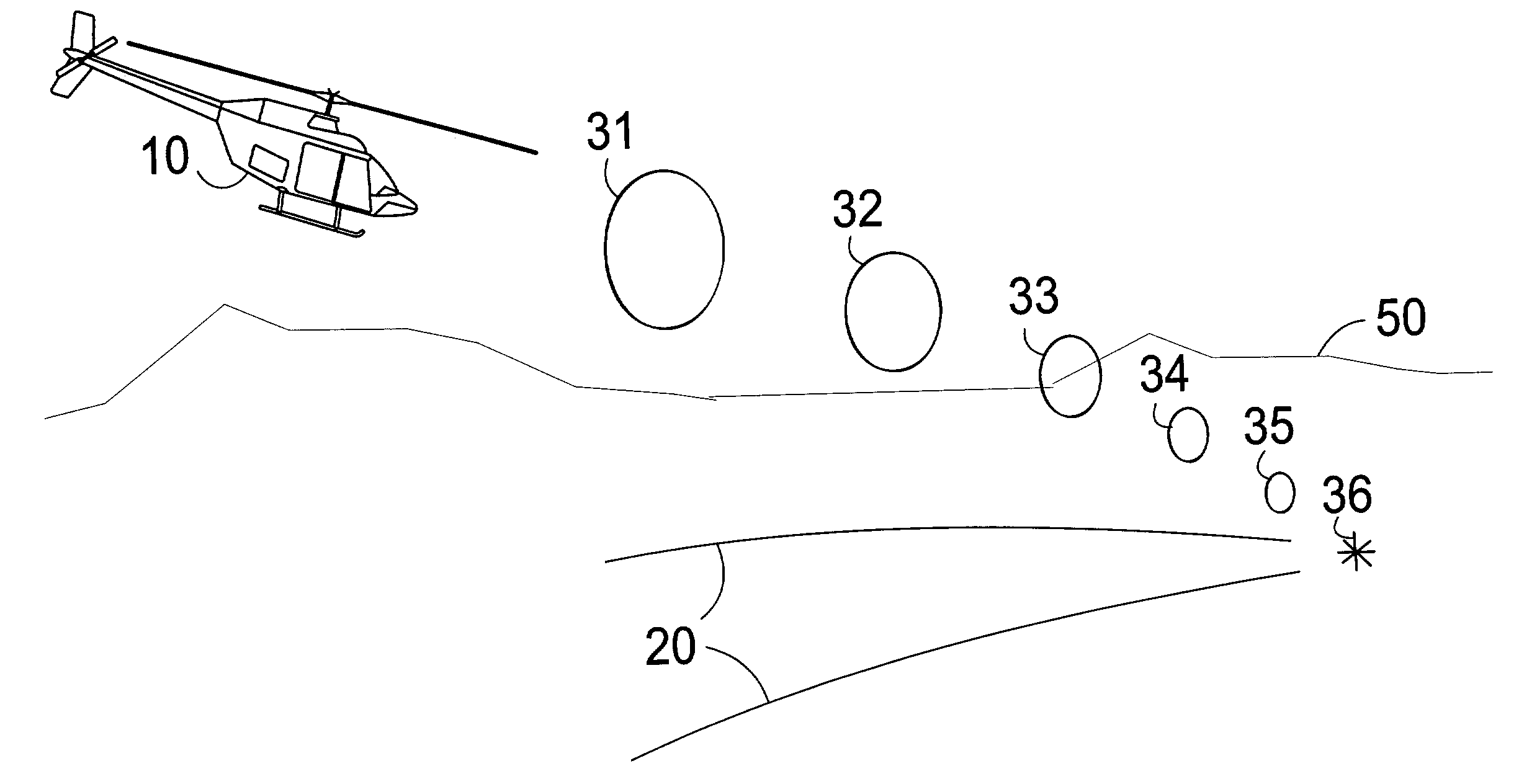
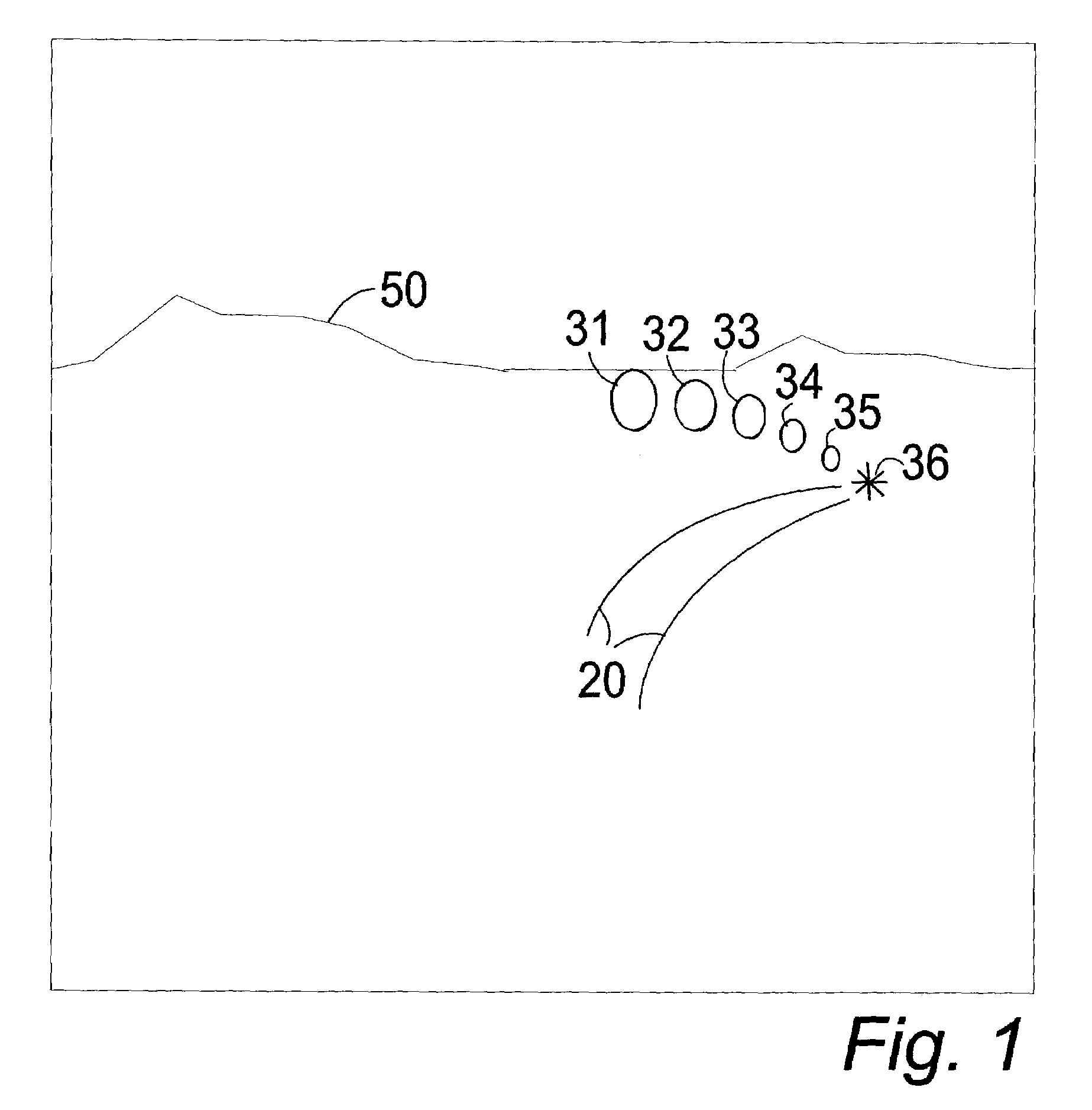
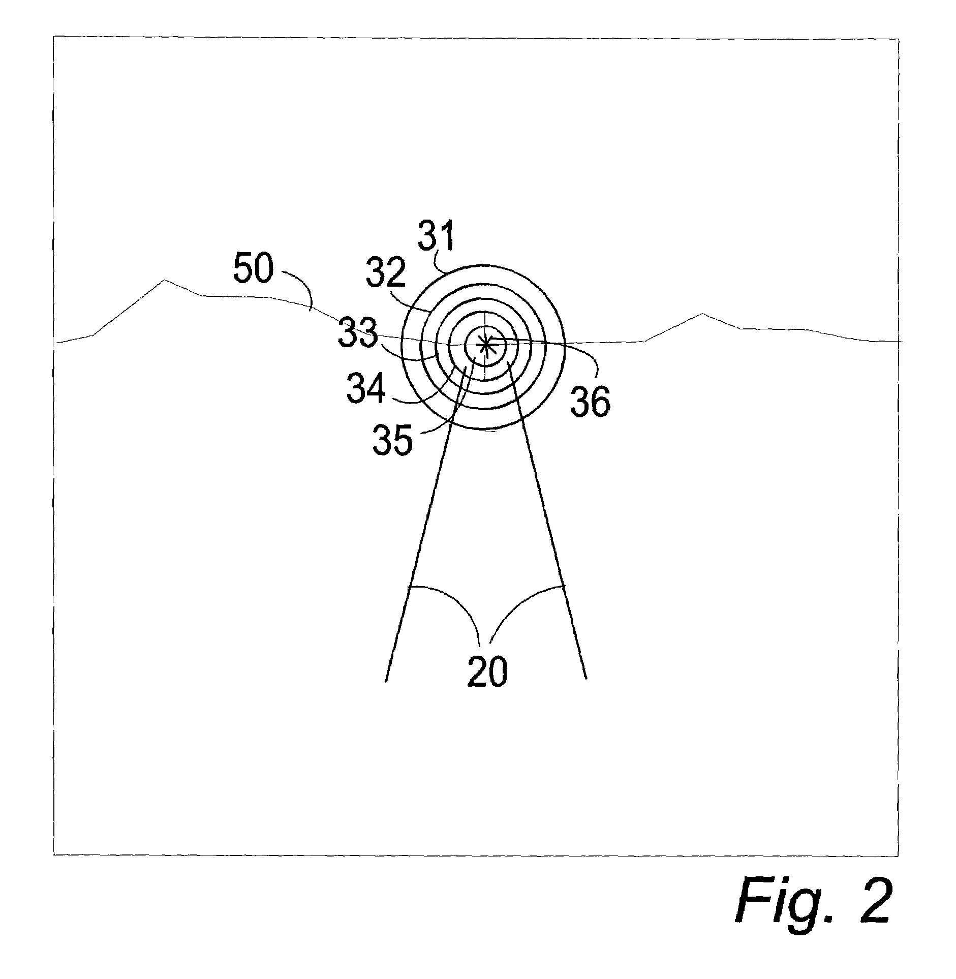
[0041]In FIGS. 1–4, a symbology system is provided for programming information relative to an aircraft's 10 future position and flight path to create a symbology representing the future position 36, and 40 including the flight path 31–35 and ground path 20 of the aircraft 10 in the visual field of a pilot.

[0042]The symbology system comprises a programmable means for gathering flight travel information in real time about an aircraft 10 from a number of instruments on the aircraft 10, using the flight travel information to create a symbology representing the aircraft 10 flight path 31–35, ground path 20 and future position information 36, and 40 superimposed on the actual visual field of a pilot of the aircraft 10, shown in FIGS. 1–4.

[0043]The symbology for the flight path comprises a series of virtual Figures 31–35 at spaced intervals in front of the aircraft 10 delineating the projected flight path of the aircraft 10 and virtual figures of various shapes and colors with other inform...


PUM


Abstract

A programmable symbology is provided that defines a series of geometric forms in the visual field of a pilot. The symbology includes a virtual representation of a predicted flight path of the aircraft and a virtual representation of a projected contact point with an external object, including the ground. The symbology also provides a virtual representation of a predicted flight path of the aircraft that is projected onto the ground below the projected flight path as a ground path predictor. The symbology further provides a critical slowing air speed indicator.

Description

BACKGROUND OF THE INVENTION[0001]1. Field of the Invention[0002]The present invention relates to visual displays for pilots of aircraft and in particular to a programmable symbology for defining a series of geometric forms in the visual field of the pilot providing a virtual representation of a predicted flight path of the aircraft and a virtual representation of a projected contact point with an external object, including the ground, and a virtual representation of the predicted flight path of the aircraft projected onto the ground below the projected flight path as a ground path predictor.[0003]2. Description of the Prior Art[0004]Aircraft, including helicopters, are highly complex systems comprised of a large number of complex, integrated subsystems that requires frequent monitoring for safe aircraft operation. Each of these subsystems generates a significant amount of status data. Additional flight complications such as nap-of-the-earth (NOE), adverse weather, and / or night flyin...

Claims


Application Information

Patent Timeline
Patent Type & Authority Patents(United States)
IPC IPC(8): G01C21/00G01C23/00
CPCG01C23/00
Inventor ROGERS, STEVEN P.ASBURY, CHARLES N.
Owner ROGERS STEVEN P
Why Eureka
Try Eureka