Dc-to-dc converter

a converter and dc technology, applied in the direction of dc-dc conversion, power conversion systems, instruments, etc., can solve the problems of increasing voltage voltages across the smoothing capacitor further lessen, and difficulties left unresolved

Inactive Publication Date: 2005-12-06
SANKEN ELECTRIC CO LTD
View PDF8 Cites 67 Cited by
  • Summary
  • Abstract
  • Description
  • Claims
  • Application Information

AI Technical Summary

Benefits of technology

[0012]Thus, during operation in light load mode, the light load mode override circuit is tripped when the output voltage of the second rectifying and smoothing circuit falls to a predefined value which is not less than a minimum allowable value at which the switch control circuit is capable of operation. The light load mode override circuit when tripped causes the voltage regulator switch to be driven continuously until the output voltage of the second rectifying and smoothing circuit returns to normal. The switch control circuit is thus kept from going out of operation due to a drop in the output voltage of the second rectifying and smoothing circuit.

Problems solved by technology

Such intermittent driving of the voltage regulator switch under light load has had some difficulties left unresolved.
The difficulties arise from the fact that, in the first rectifying and smoothing circuit which powers the load as aforesaid, the voltage across the smoothing capacitor rises during each switching period (i.e. period of time during which the switch is driven) and diminishes during the ensuing nonswitching period.
The smoothing capacitors of both first and second rectifying and smoothing circuits are not charged during the restart periods, so that the voltages across these capacitors further lessens, making it difficult or even impossible to feed the load as required.
These solutions are objectionable because such a transformer tertiary and such a smoothing capacitor would incur greater power losses.

Method used


Image

  • Dc-to-dc converter
  • Dc-to-dc converter
  • Dc-to-dc converter

Examples


embodiment

of FIG. 6

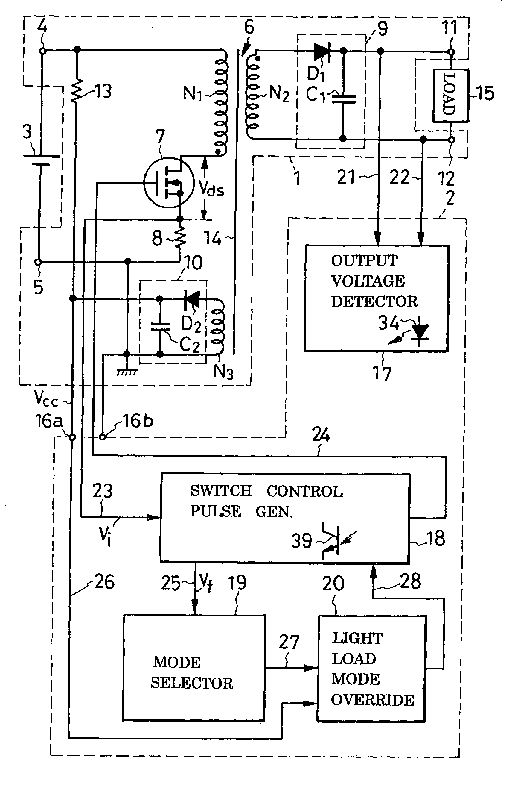
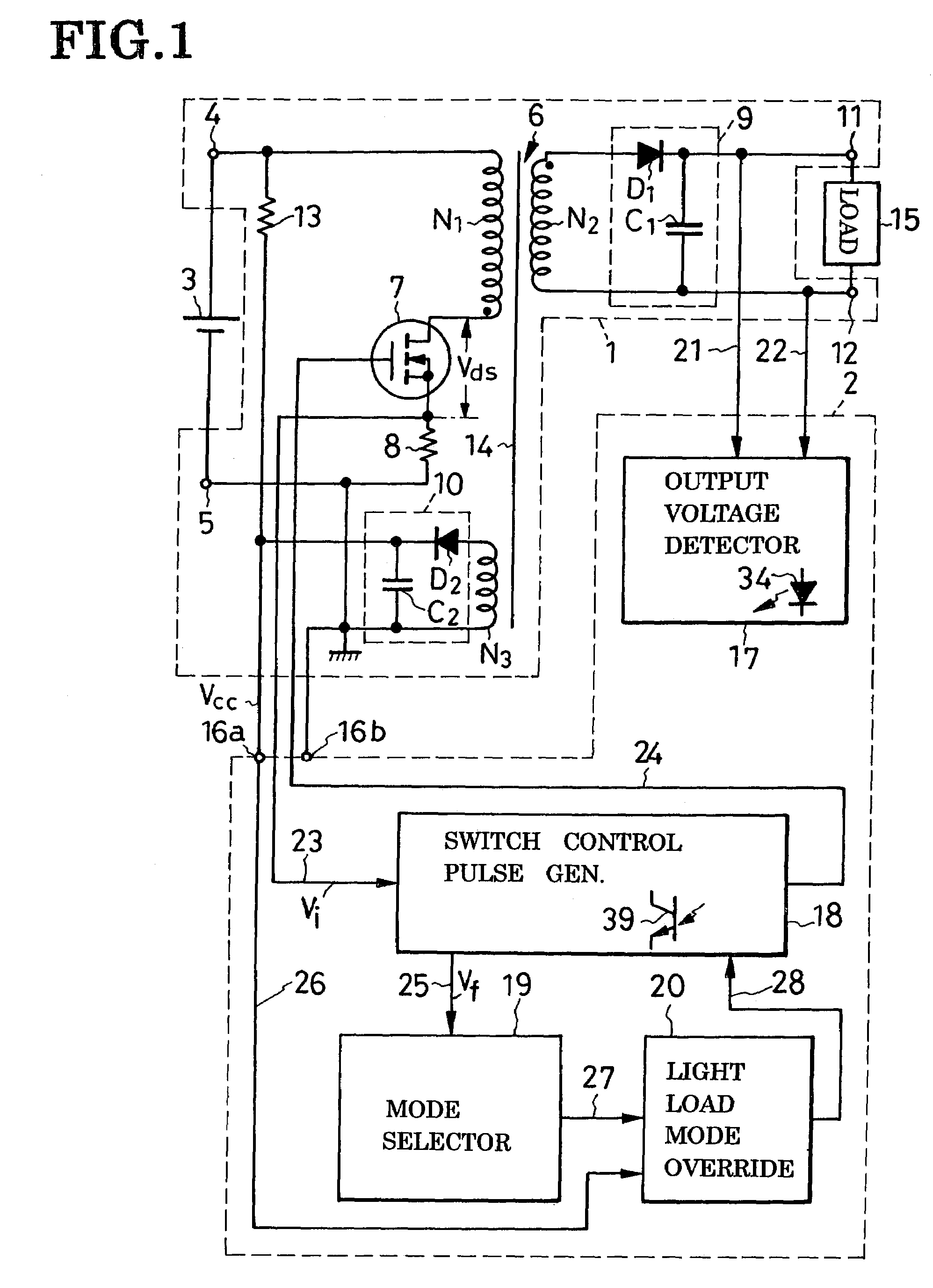
[0079]The dc-to-dc converter of FIG. 6 includes a modified dc-to-dc converter circuit 1a and the switch control circuit 2 of the same construction as its FIG. 1 counterpart. The modified dc-to-dc converter circuit 1a includes a transformer 6a which has no secondary winding; instead, has the first rectifying and smoothing circuit 9 is connected in parallel with the switch 7. This embodiment is identical with that of FIGS. 1–5 in all the other details of construction.

[0080]Energy is stored during each conducting period of the switch 7 on the inductive transformer primary N1 as then the rectifying diode D1 of the first rectifying and smoothing circuit 9 is reverse biased. The thus-stored energy is released from the transformer primary N1 during the subsequent nonconducting period of the switch 7 as then the rectifying diode D1 is forward biased. The smoothing capacitor C1 of the first rectifying and smoothing circuit 9 is therefore charged by the resultant of the voltage acros...


PUM


Abstract

A transformer has a primary winding connected between a pair of dc input terminals via a switch, a secondary winding connected between a pair of output terminals via a first rectifying and smoothing circuit, and a tertiary winding connected to a second rectifying and smoothing circuit for feeding a switch control circuit. Included in the switch control circuit is a switch control pulse generator circuit whereby the switch is driven to provide a constant dc voltage at the output terminals. A mode selector circuit is connected to the switch control pulse generator circuit to cause the switch to be driven continuously under normal load, and at intervals under light load. The intermittent driving of the switch is suspended, and the switch driven continuously, in the event of a drop in the output voltage of the second rectifying and smoothing circuit to a predefined value during operation in light load mode.

Description

CROSS REFERENCE TO RELATED APPLICATIONS[0001]This is a continuation of Application PCT / JP03 / 10634, filed Aug. 22, 2003, which claims priority to Japanese Patent Application No. 2002-259290 filed Sep. 4, 2002.BACKGROUND OF THE INVENTION[0002]This invention relates generally to dc-to-dc converters which convert one unidirectional voltage into another and, more particularly, to a dual-mode dc-to-dc converter wherein the voltage regulator switch for holding the output voltage constant is driven (i.e. turned on and off) continuously under normal load and at intervals under light load, with a view to reduction of switching loss. Still more particularly, the invention deals with how to override the light load mode when the power requirement of the load becomes still lower.[0003]The dc-to-dc converter of the type herein under consideration generally comprises a transformer having a primary winding connected across a dc power supply, and a secondary winding connected across a load via a rect...

Claims


Application Information

Patent Timeline
Patent Type & Authority Patents(United States)
IPC IPC(8): H02M3/335
CPCH02M3/33523H02M3/28
Inventor YAMADA, TOMOYASU
Owner SANKEN ELECTRIC CO LTD
Why Eureka
Try Eureka