
Axially displacing slip-clutch for rotor-type sprinkler

a technology of rotor-type sprinklers and slip-clutches, which is applied in the direction of spraying apparatuses, movable spraying apparatuses, etc., can solve the problems of damage to the same, clutches and automatic arc return mechanisms that have heretofore been developed for rotor-type sprinklers, and spray water outside the intended arc of coverag

Active Publication Date: 2010-11-09
HUNTER INDUSTRIES
View PDF27 Cites 29 Cited by
  • Summary
  • Abstract
  • Description
  • Claims
  • Application Information

AI Technical Summary

Benefits of technology

[0007]In accordance with the invention, a sprinkler includes a riser, an impeller mounted in the riser, and a nozzle rotatably mounted at an upper end of the riser. A drive assembly including a reduction gear train couples the

Problems solved by technology

Vandals frequently twist the nozzle turret of rotor-type sprinklers which causes them to spray water outside their intended arc of coverage, often onto roads and sidewalks.
When a vandal twists the nozzle turret of a rotor-type sprinkler to “back drive” the sprinkler, i.e. rotate the nozzle turret in a direction opposite the direction it is currently being driven by its turbine, strong rotational forces are transmitted to the reversing mechanism and reduction gear train, frequently damaging the same.
Clutches and automatic arc return mechanisms that have heretofore been developed for rotor-type sprinklers have been too complex, required too many parts and / or been too unreliable.
They have also not been suitable for retrofitting, i.e. installation into existing rotor-type sprinklers not originally designed with clutches to prevent back driving.

Method used


Image

  • Axially displacing slip-clutch for rotor-type sprinkler
  • Axially displacing slip-clutch for rotor-type sprinkler
  • Axially displacing slip-clutch for rotor-type sprinkler

Examples


Embodiment Construction

[0026]The entire disclosures of U.S. Pat. No. 3,107,056 granted to Hunter on Oct. 15, 1963; U.S. Pat. No. 4,568,024 granted to Hunter on Feb. 4, 1986; U.S. Pat. No. 4,718,605 granted to Hunter on Jan. 12, 1988; U.S. Pat. No. 6,050,502 granted to Clark on Apr. 18, 2000; U.S. Pat. No. 6,840,460 granted to Clark on Jan. 11, 2005; and pending U.S. patent application Ser. No. 11 / 139,725 filed by Crooks on May 27, 2005, are hereby incorporated by reference.

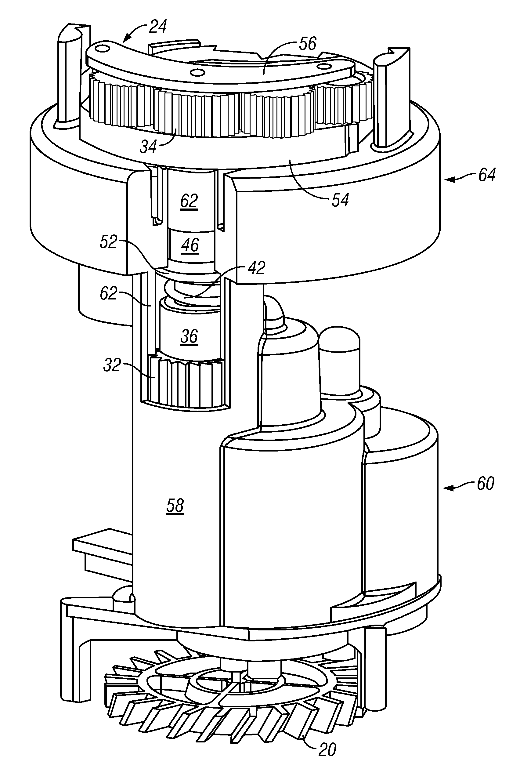
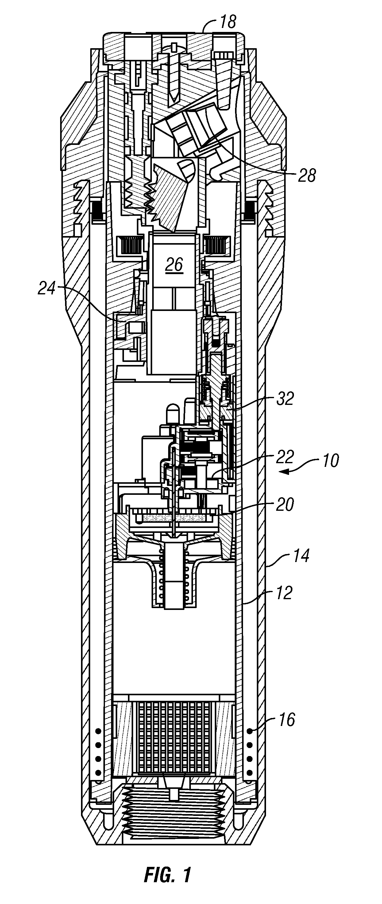
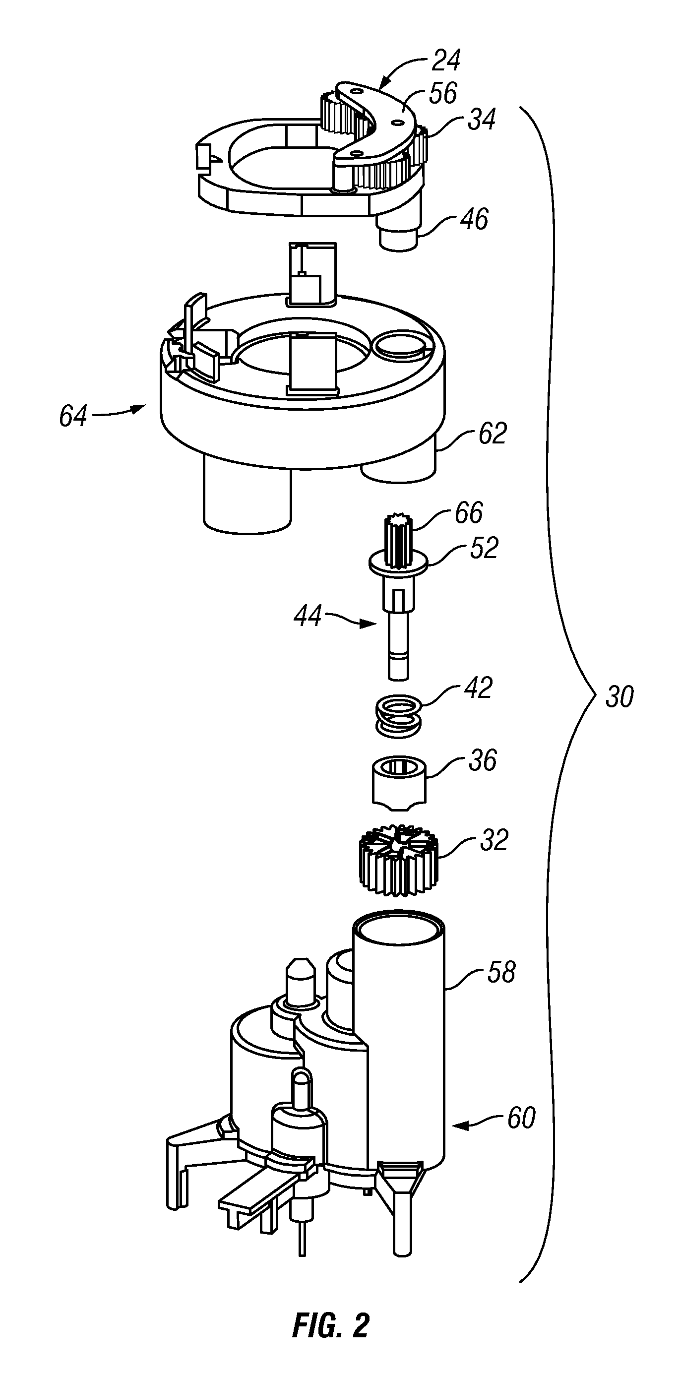
[0027]Referring to FIG. 1, in accordance with an embodiment of the invention, a rotor-type sprinkler 10 includes a tubular riser 12 vertically reciprocable within an outer case 14 and normally held in a retracted position by a relatively large stainless steel coil spring illustrated diagrammatically by dots 16. A cylindrical nozzle head or turret 18 is rotatably mounted at the upper end of the riser 12. A turbine 20, reduction gear train 22, and a reversing mechanism 24 are mounted in the riser 12 and rotate the nozzle turret 18 through...


PUM


Abstract

A sprinkler includes a riser, an impeller mounted in the riser, and a nozzle rotatably mounted at an upper end of the riser. A drive assembly including a reduction gear train couples the impeller and the nozzle. A clutch in the drive assembly includes a clutch member having an axis of rotation that provides a positive drive connection under a normal load and axially displaces and slips under an excessive load.

Description

CROSS-REFERENCE TO RELATED APPLICATIONS[0001]This application is a continuation-in-part of pending U.S. patent application Ser. No. 11 / 558,287 filed Nov. 9, 2006, which was a continuation of now-abandoned U.S. patent application Ser. No. 11 / 465,368 filed Aug. 17, 2006. The subject application claims priority from the filing dates of both of said applications under 35 U.S.C. Sections 119 and 120.FIELD OF THE INVENTION[0002]The present invention relates to sprinklers used to irrigate turf and landscaping, and more particularly, to clutch mechanisms designed to prevent drive assembly damage when vandals twist the nozzle turret of a rotor-type sprinkler.BACKGROUND OF THE INVENTION[0003]A common type of irrigation sprinkler used to water turf and landscaping is referred to as a rotor-type sprinkler. It typically includes a riser that telescopes from an outer casing. The riser encloses a turbine that rotates a nozzle turret at the top of the riser through a reduction gear train and revers...

Claims


Application Information

Patent Timeline
IPC IPC(8): B05B3/04
CPCB05B3/0431B05B15/10B05B15/74
Inventor ANUSKIEWICZ, RONALD H.CAPEN, KYLE R.
Owner HUNTER INDUSTRIES
Learn More