Series & parallel combined dual power drive system

a dual-power drive, parallel technology, applied in the direction of electric generator control, electric devices, machines/engines, etc., can solve the problems of consuming too much space, heavy and high cos

Active Publication Date: 2005-10-20
YANG TAI HER
View PDF13 Cites 28 Cited by
  • Summary
  • Abstract
  • Description
  • Claims
  • Application Information

AI Technical Summary

Problems solved by technology

Series combined power system: the engine is used to drive the motor, in turn, the power from the generator drives the motor to create rotation kinetics to drive the load; this system has its flaw in a wild diff

Method used


Image

  • Series & parallel combined dual power drive system
  • Series & parallel combined dual power drive system
  • Series & parallel combined dual power drive system

Examples


Embodiment Construction

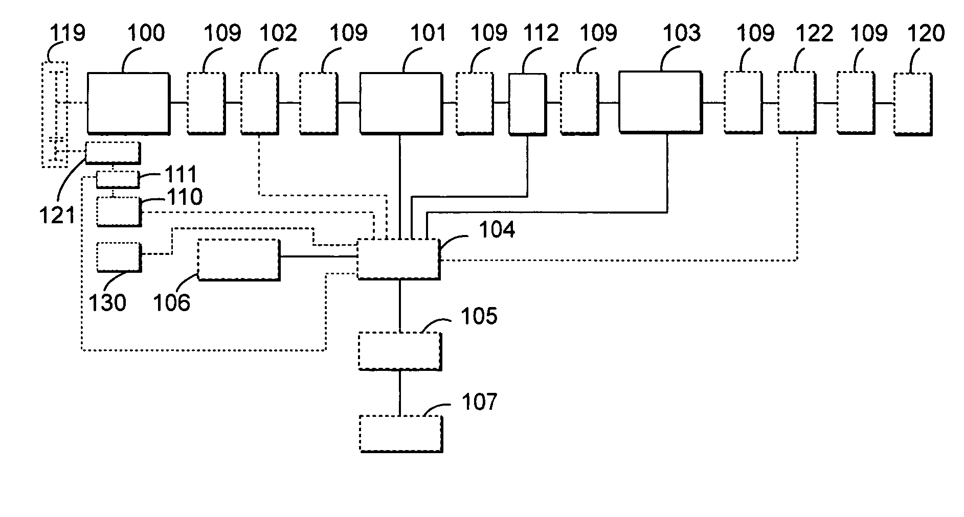
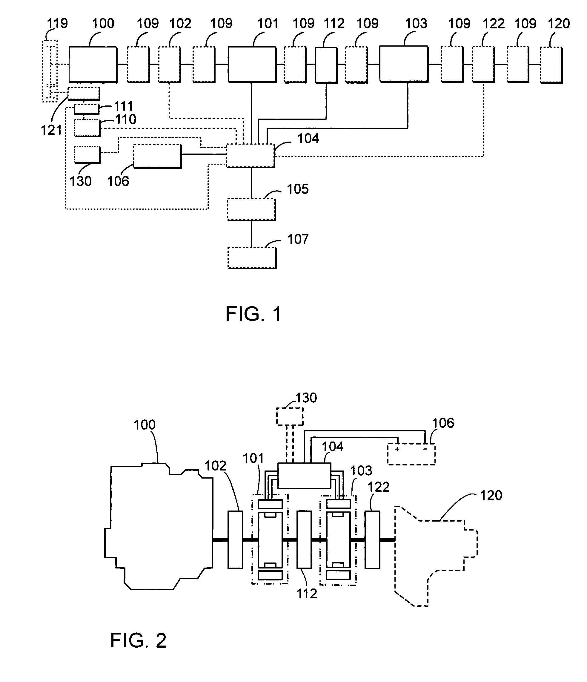
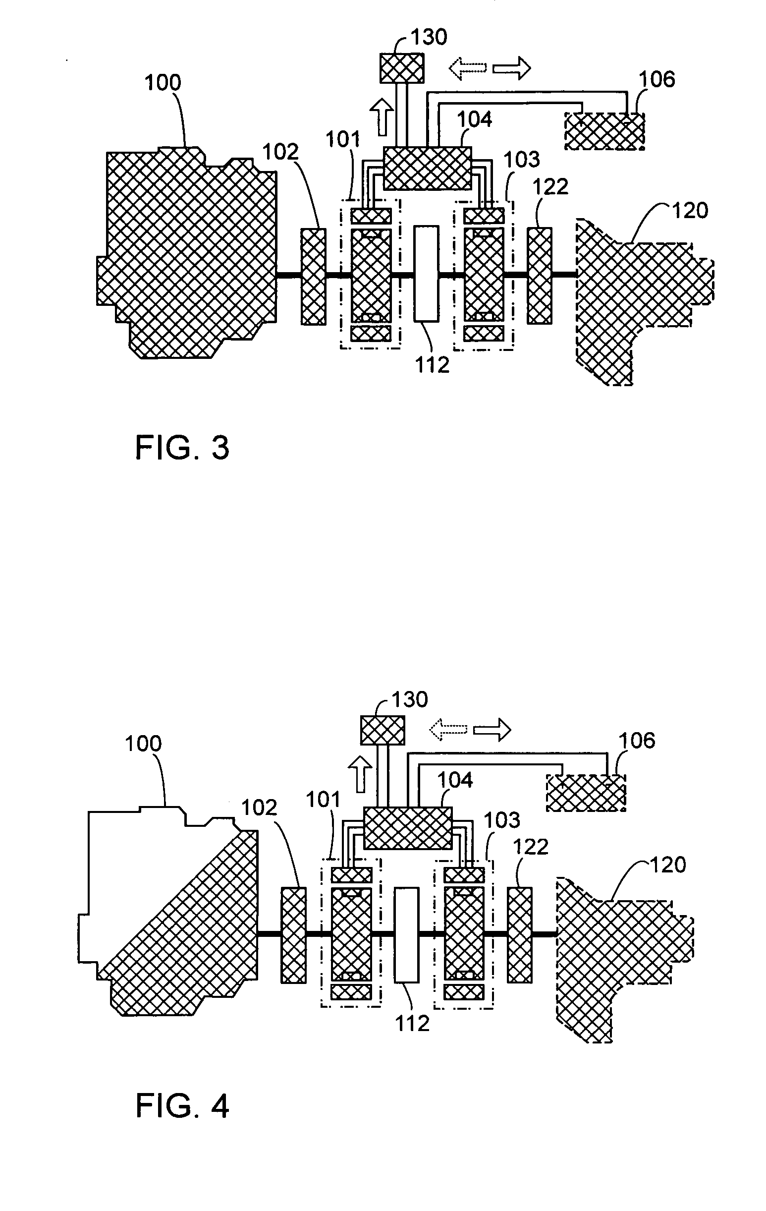
[0160] The present invention of a series and parallel combined dual power system operates as a series combined power system, or as a parallel combined power system. Wherein, when an internal combustion engine is used as an active rotation power source, the rotation kinetics outputted form the engine is used to directly drive a load in case of a normal load; the system is switched to operate as the series combined power system as required with the power from the engine to drive a primary dynamo-electric unit for functioning as a generator to drive a secondary dynamo-electric unit for functioning as a motor to output rotation kinetics to drive the load in case of a light load.

[0161] The series and parallel dual power system may be adapted with an operation rechargeable device. If the rechargeable device is adapted and in case of a heavy load, the power from the rechargeable device drives either or both of the primary and the secondary dynamo-electric units to function as a motor, and...


PUM


Abstract

A series and parallel combined dual power system operates as a series combined power system, or as a parallel combined power system; the power from an engine directly drive the load; the system engages in the operation as the series combined power system incase of a light load; the load is driven by the engine in case of a normal load; an optional rechargeable device is adapted to the system; either or both of a primary and a secondary dynamo-electric units functions as a motor on the power from the rechargeable device to jointly drive the load with the power from the engine; and functions to provide power drive in case of a light load.

Description

CROSS-REFERENCE TO RELATED APPLICATION [0001] This application is a Continuation-In-Part of U.S. patent application, Ser. No. 10 / 851,207, file May 24, 2004, which is a Continuation-In-Part of U.S. patent application, Ser. No. 10 / 826,392, filed Apr. 19, 2004.BACKGROUND OF THE INVENTION [0002] (a) Field of the Invention [0003] The present invention is related to a series and parallel combined dual power drive system for the engine functioning as the active rotation power source to directly drive a load, the system provides the following functions: [0004] Operating as a series combined power system, wherein, the engine drives a primary dynamo-electric unit to function as a generator with the power generated to drive a secondary dynamo-electric unit to output mechanical rotation kinetics to drive the load and regulate the engine to operate at a constant speed yielding higher energy efficiency; the constant speed operation is defined as the range of operation speed wherein the engine is ...

Claims


Application Information

Patent Timeline
IPC IPC(8): B60K6/442B60L50/15B60L50/16B60W10/02B60W10/06B60W10/08B60W30/182
CPCB60K6/442B60L2260/12B60W10/06B60W10/08B60W10/26Y10S903/946B60W30/182Y02T10/56Y02T10/6234Y02T10/6286B60W20/00B60W20/20B60L50/16B60L50/40B60L2260/52B60L2220/14B60L2220/12B60L2220/16B60L2220/20B60L2240/441B60L2240/507B60L2240/486B60L15/2045B60L15/2009B60L7/14B60L7/12B60L50/61Y02T10/72Y02T10/84Y02T10/40Y02T10/62Y02T10/64Y02T10/70Y02T10/7072
Inventor YANG, TAI-HER
Owner YANG TAI HER
Why Eureka
Try Eureka