Check patentability & draft patents in minutes with Patsnap Eureka AI!

Reverse-direction-staple system and method

a reverse-direction and clamping technology, applied in the field of electric machines, can solve the problems of increasing adding cost and time to the manufacturing process, and limiting the height of the stack,

Inactive Publication Date: 2005-12-13
GENERAL ELECTRIC CO
View PDF6 Cites 4 Cited by
  • Summary
  • Abstract
  • Description
  • Claims
  • Application Information

AI Technical Summary

Problems solved by technology

The welding and cleating methods add cost and time to the manufacturing process since these methods are performed after the lamination plates are pressed and stacked.
However, the conventional interlocked lamination plates can form a core that is “spongy” or breaks apart during subsequent manufacturing operations, which has limited the height of the stack.
Additionally, the conventional interlocked lamination plates require extreme accuracy and tolerances in the punching operation, which can add cost and complexity to the manufacturing process.
Moreover, the position and number of the interlocking protrusion / indentations can cause eddy currents in the electric machine, which reduces the efficiency of the electric machine.

Method used


Image

  • Reverse-direction-staple system and method
  • Reverse-direction-staple system and method
  • Reverse-direction-staple system and method

Examples


Embodiment Construction

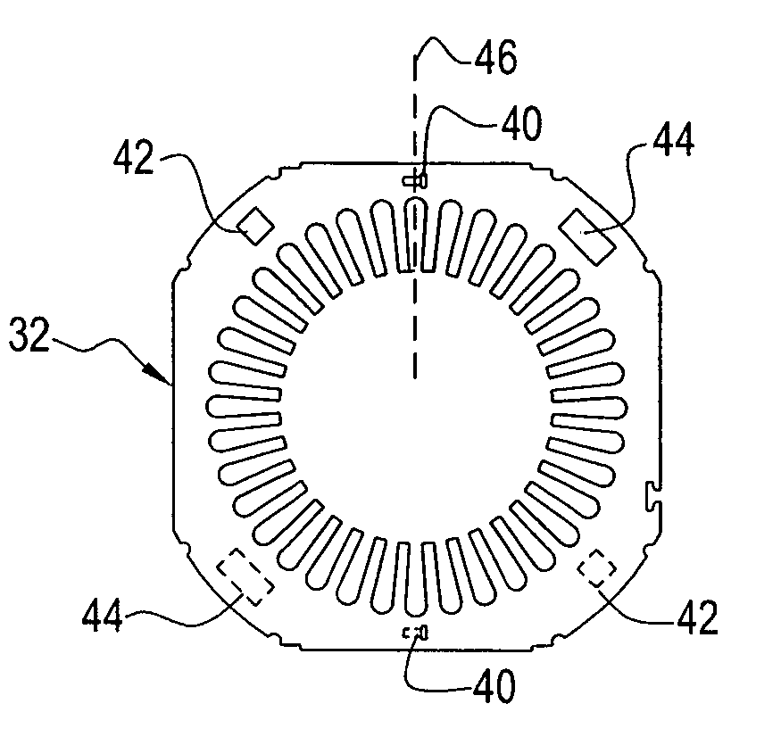
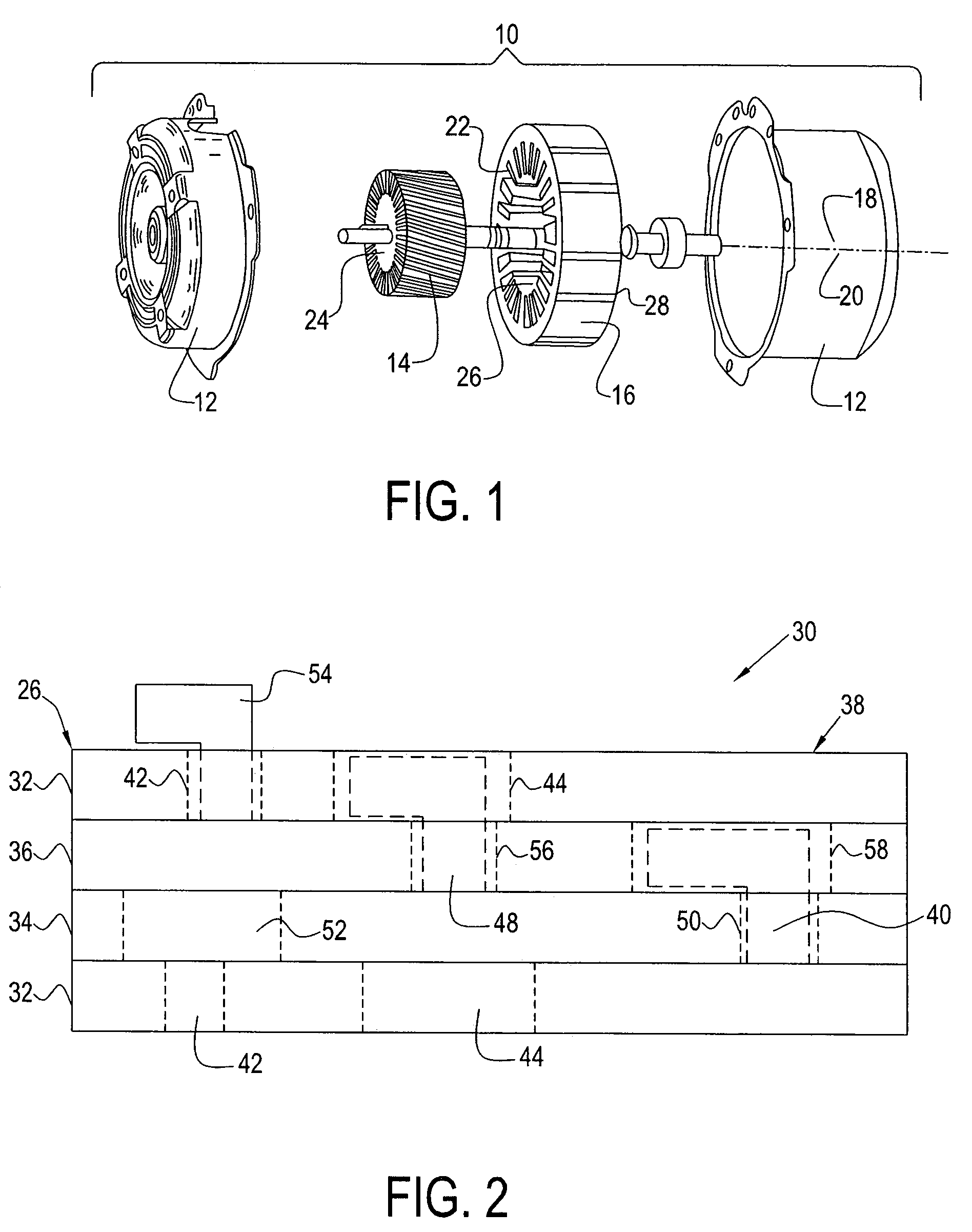
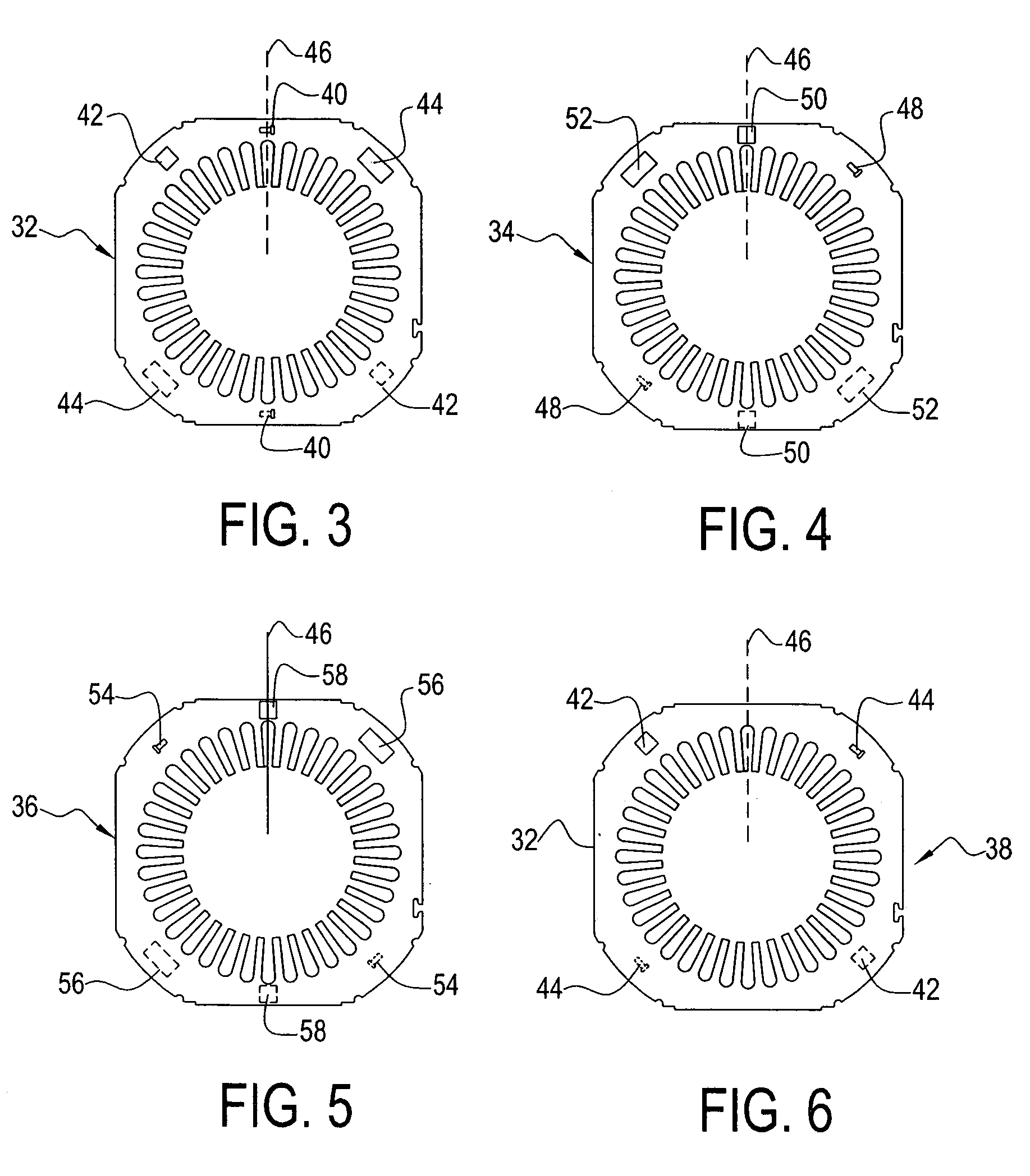
[0018]Referring to the drawings and in particular to FIG. 1, there is shown an electric machine generally illustrated by reference numeral 10. Electric machine 10 can be a motor, a generator, an alternator, a starter-generator, a motor-generator, and others. It should be recognized that various components of electric machine 10 have been omitted from FIG. 1 for purposes of clarity.

[0019]Electric machine 10 can include a housing 12 having a rotor 14 and a stator 16 disposed therein. In the illustrated example, stator 16 is the stationary portion of electric machine 10 that is mounted to and within housing 12. Rotor 14 is the rotating portion of electric machine 10 that is positioned for rotation within stator 16.

[0020]Stator 16 defines a first longitudinal axis 18, while rotor 14 defines a second longitudinal axis 20. Rotor 14 is positioned in stator 16 such that the axes 18, 20 of the rotor and the stator are collinear so that an air gap 22 is defined therebetween. Gap 22 permits ro...


PUM


Abstract

A reverse-direction staple system for a plurality of members to be stacked on top of one another is provided. The system includes an upwardly extending staple, a staple access hole, and a staple clearance opening defined in each member to be stacked. The upwardly extending staple of each member extends through the staple access hole of a subsequent member and forms a bent staple over the subsequent member. In addition, the bent staples are received in the staple clearance opening of a second subsequent member.

Description

CROSS-REFERENCE TO RELATED APPLICATIONS[0001]This application is a continuation-in-part of U.S. application Ser. No. 09 / 682,269 filed on Aug. 11, 2001 now U.S. Pat. No. 6,722,015 and a continuation-in-part of U.S. application Ser. No. 09 / 682,277 filed on Aug. 13, 2001 now U.S. Pat. No. 6,847,285, the contents of each of which are incorporated herein by reference.BACKGROUND OF THE INVENTION[0002]The present disclosure relates to electric machines and more specifically to a reverse-direction-staple system and method for securing lamination plates of an electric machine to one another.[0003]Electric machines, such as motors, generators, alternators, starter-generators, typically have a stator core and / or a rotor core formed of a plurality of stacked lamination plates. The stacked lamination plates are commonly held together along the axial dimension by welding, cleating, or conventional interlocking.[0004]The welding and cleating methods add cost and time to the manufacturing process s...

Claims


Application Information

Patent Timeline
IPC IPC(8): H01F3/02H01F27/245H02K1/06H02K15/02
CPCH01F3/02H02K1/06H02K15/02H01F27/2455
Inventor SIROIS, ROBERT D.
Owner GENERAL ELECTRIC CO
Features
  • R&D
  • Intellectual Property
  • Life Sciences
  • Materials
  • Tech Scout
  • Unparalleled Data Quality
  • Higher Quality Content
  • 60% Fewer Hallucinations
Learn More