Projection type image display device

a display device and projection type technology, applied in the field of projection type image display devices, can solve the problems of color synthesizing prisms that become expensive, and the difference in the spectral/transmitted cutoff wavelength, and achieve the effects of simple, inexpensive structure, and correction of color unevenness

Inactive Publication Date: 2005-12-13
CANON KK
View PDF15 Cites 4 Cited by
  • Summary
  • Abstract
  • Description
  • Claims
  • Application Information

AI Technical Summary

Benefits of technology

[0011]It is therefore an object of the present invention to provide a projection type image display device capable of correcting color unevenness that easily occurs when a lens group with positive refractive power is disposed between a color synthesizing optical element, such as a color synthesizing prism, and an image display element by a simple, inexpensive structure, irrespective of a horizontal or vertical direction of a projected image.
[0013]Thereby, it is possible to correct the nonuniformity (color unevenness) in the brightness level that easily occurs when the lens group with positive refractive power is disposed between the color synthesizing optical element and the image display element by a simple, inexpensive structure, irrespective of a horizontal or vertical direction of the projected image, and is possible to project and display an image with high picture quality and with no color unevenness.
[0014]Additionally, when a gradient membrane is used as a dichroic membrane in order to correct color unevenness in a specific direction, color unevenness in a direction that cannot be optically corrected by this gradient membrane can be electrically corrected with ease.

Problems solved by technology

Therefore, disadvantageously, for the example, the incidence angle of the light upon the dichroic membrane has a difference between the right and the left of the image, and thereby a difference arises in the spectral / transmitted cutoff wavelength in the dichroic membrane.
However, there is a problem in that, usually, color unevenness can be simply corrected only in one direction in the thus formed gradient membrane, so that color unevenness in each direction cannot be sufficiently corrected, and, in addition, a color synthesizing prism becomes expensive due to the formation of the gradient membrane.

Method used


Image

  • Projection type image display device
  • Projection type image display device
  • Projection type image display device

Examples


Embodiment Construction

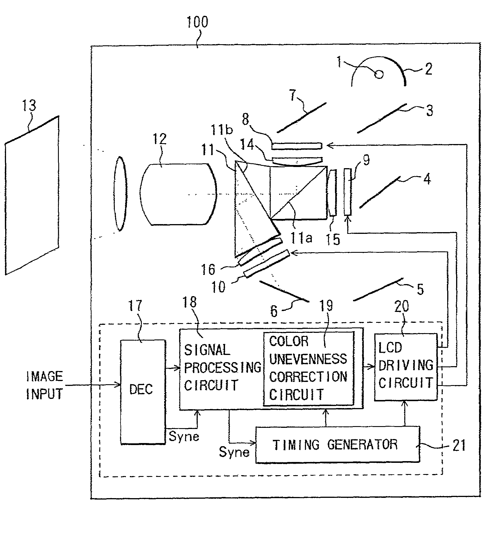
[0024]FIG. 1 shows a structure of a liquid crystal projector (projection type image display device), which is an embodiment of the present invention.

[0025]First, an optical system in a liquid crystal projector 100 will be described. In FIG. 1, white light emitted from a light source 1 is transformed into substantially parallel rays of light by a parabolic mirror 2, a reflecting mirror (not shown), and a lens group (not shown).

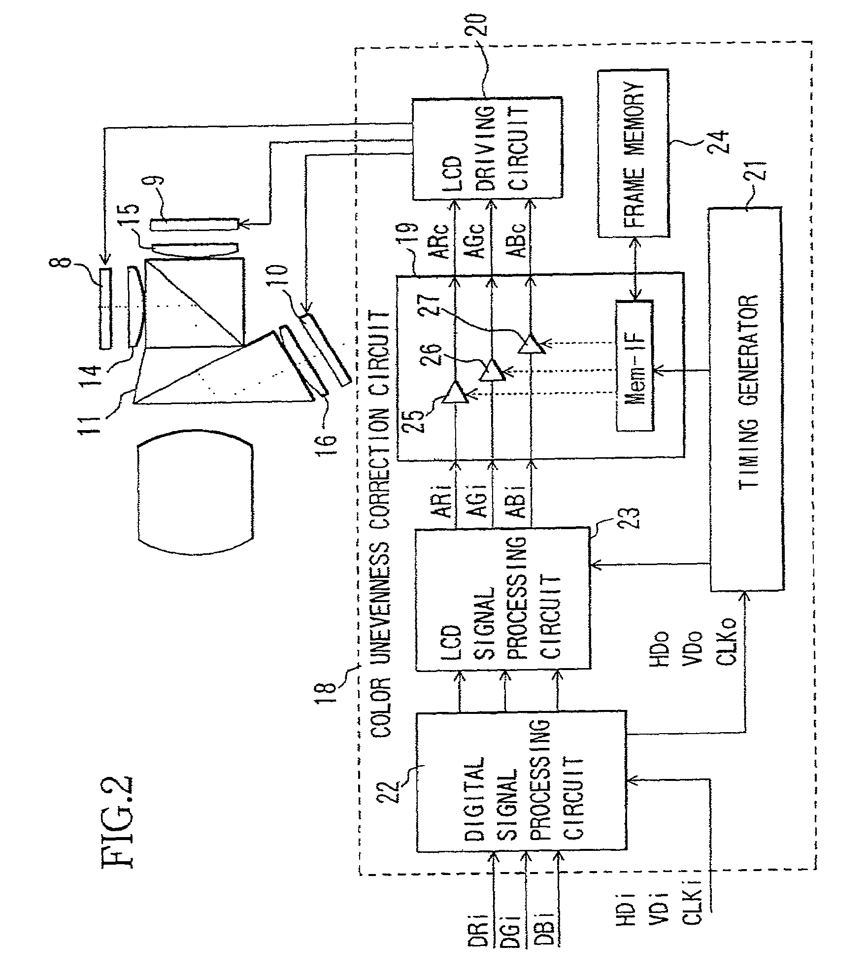
[0026]The substantially parallel light is subjected to color separation by dichroic mirrors 3 and 4, highly reflecting mirrors 5, 6 and 7, and a lens group (not shown) so as to turn into each color of red, green and blue, and is condensed onto liquid crystal panels (image display elements) 8, 9 and 10 disposed for each color.

[0027]Light rays that have entered the liquid crystal panels 8, 9 and 10 are then modulated by the liquid crystal panels 8, 9 and 10, respectively, that display images, thereby producing spatially modulated light in accordance with the disp...


PUM

PropertyMeasurementUnit
thicknessaaaaaaaaaa
brightnessaaaaaaaaaa
incident angleaaaaaaaaaa

Abstract

A projection type image display device includes a plurality of image display elements that perform modulation of light rays in accordance with an image signal, a color synthesizing optical element for synthesizing light rays having mutually different wavelength ranges that have been modulated by these image display elements by use of a dichroic membrane, lens groups having a positive refractive power as a whole that are disposed between the image display element and the color synthesizing optical element, and a projection optical system for projecting an image synthesized by the color synthesizing optical element. The projection type image display device further includes a storage circuit for storing data used to correct the brightness irregularity of a projected image, and a brightness irregularity correcting circuit for correcting brightness irregularity of a projected image on the basis of the data stored in the storage circuit.

Description

BACKGROUND OF THE INVENTION[0001]1. Field of the Invention[0002]The present invention relates to a projection type image display device, such as a liquid crystal projector, including a color synthesizing optical system that uses a dichroic membrane, or film.[0003]2. Description of the Related Art[0004]Conventionally, various devices have been proposed as a projection type image display device, such as a liquid crystal projector, including a color synthesizing optical system.[0005]A conventional projection type image display device will now be described with reference to FIG. 8. In FIG. 8, white light emitted from a light source 201 is transformed into substantially parallel rays of light by a parabolic mirror 202, a reflecting mirror (not shown), and a lens group (not shown).[0006]The substantially parallel rays of light are subjected to color separation by dichroic mirrors 203 and 204, highly reflecting mirrors 205, 205 and 207, and a lens group (not shown), and are condensed to li...

Claims


Application Information

Patent Timeline
Patent Type & Authority Patents(United States)
IPC IPC(8): G03B21/00G02F1/13G09G3/20G09G3/34G09G3/36H04N5/202H04N5/57H04N5/74H04N9/31H04N9/68H04N9/69
CPCG09G3/3611H04N9/3182H04N9/3197H04N9/68H04N9/69G09G3/34G09G2320/0233G09G2320/0242G09G2320/0285H04N5/202H04N5/57H04N2005/745
Inventor YOKOYAMA, TOSHIHIKOSUZUKI, YASUO
Owner CANON KK
Why Eureka
Try Eureka