Projection type image display device

Inactive Publication Date: 2005-09-22
CANON KK
View PDF13 Cites 8 Cited by
  • Summary
  • Abstract
  • Description
  • Claims
  • Application Information

AI Technical Summary

Benefits of technology

[0011] It is therefore an object of the present invention to provide a projection type image display device capable of correcting color unevenness that easily occurs when a lens group with positive refractive power is disposed

Problems solved by technology

Therefore, disadvantageously, for the example, the incidence angle of the light upon the dichroic membrane has a difference between the right and the left of the image, and thereby a difference arises in the spectral/transmitted cutoff wavelength in the dichroic membrane.
However, there is a problem in

Method used


Image

  • Projection type image display device
  • Projection type image display device
  • Projection type image display device

Examples


Example

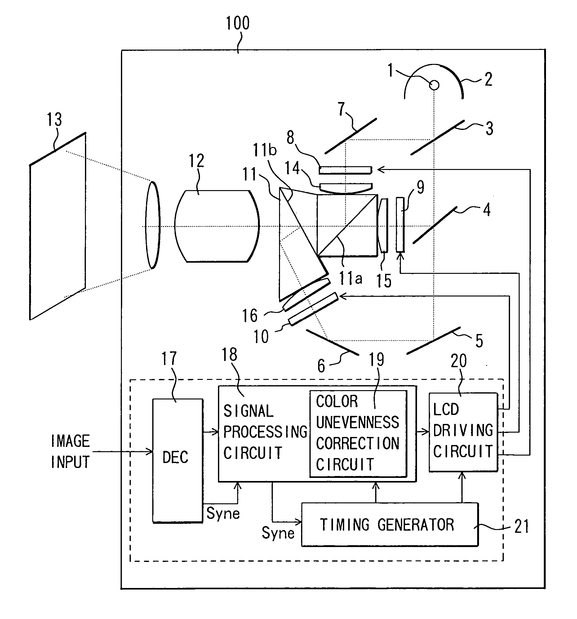
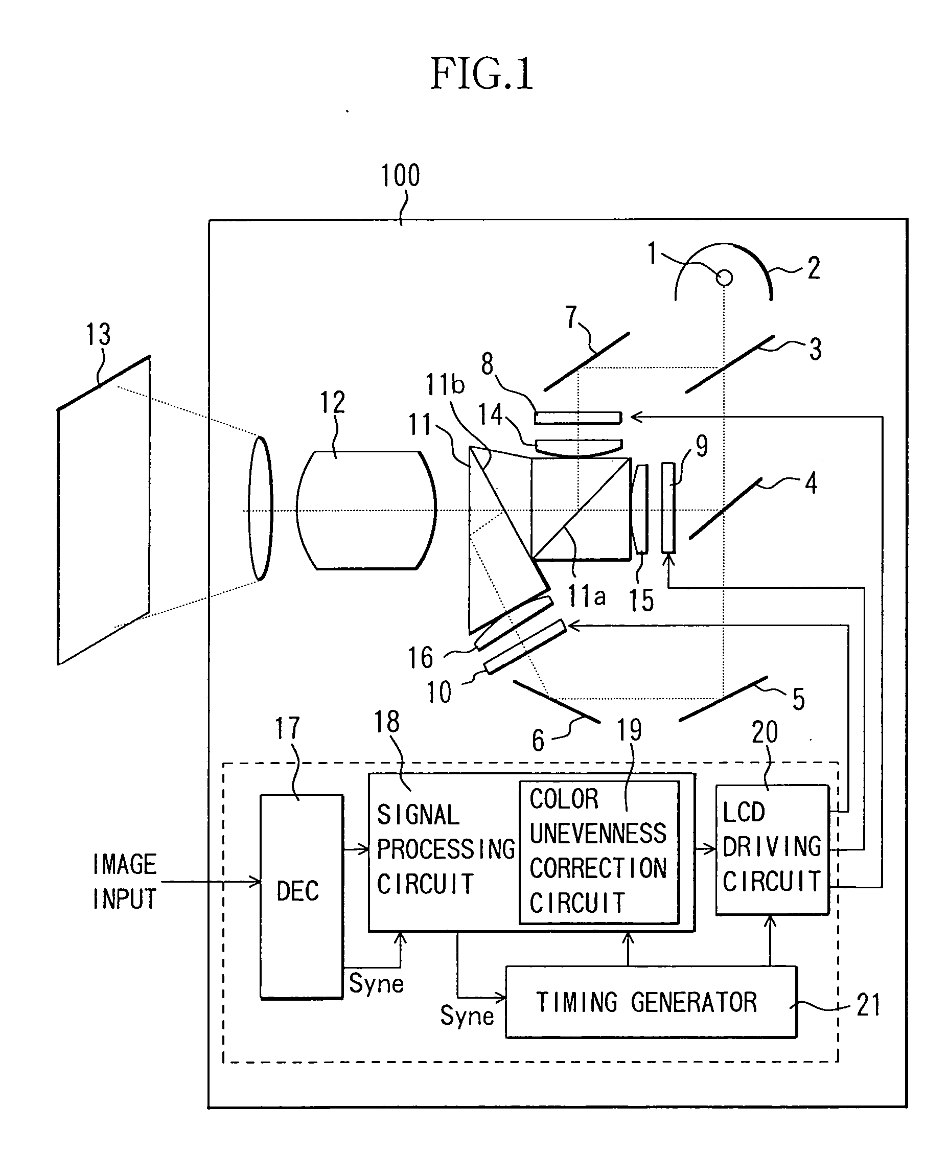
[0024]FIG. 1 shows a structure of a liquid crystal projector (projection type image display device), which is an embodiment of the present invention.

[0025] First, an optical system in a liquid crystal projector 100 will be described. In FIG. 1, white light emitted from a light source 1 is transformed into substantially parallel rays of light by a parabolic mirror 2, a reflecting mirror (not shown), and a lens group (not shown).

[0026] The substantially parallel light is subjected to color separation by dichroic mirrors 3 and 4, highly reflecting mirrors 5, 6 and 7, and a lens group (not shown) so as to turn into each color of red, green and blue, and is condensed onto liquid crystal panels (image display elements) 8, 9 and 10 disposed for each color.

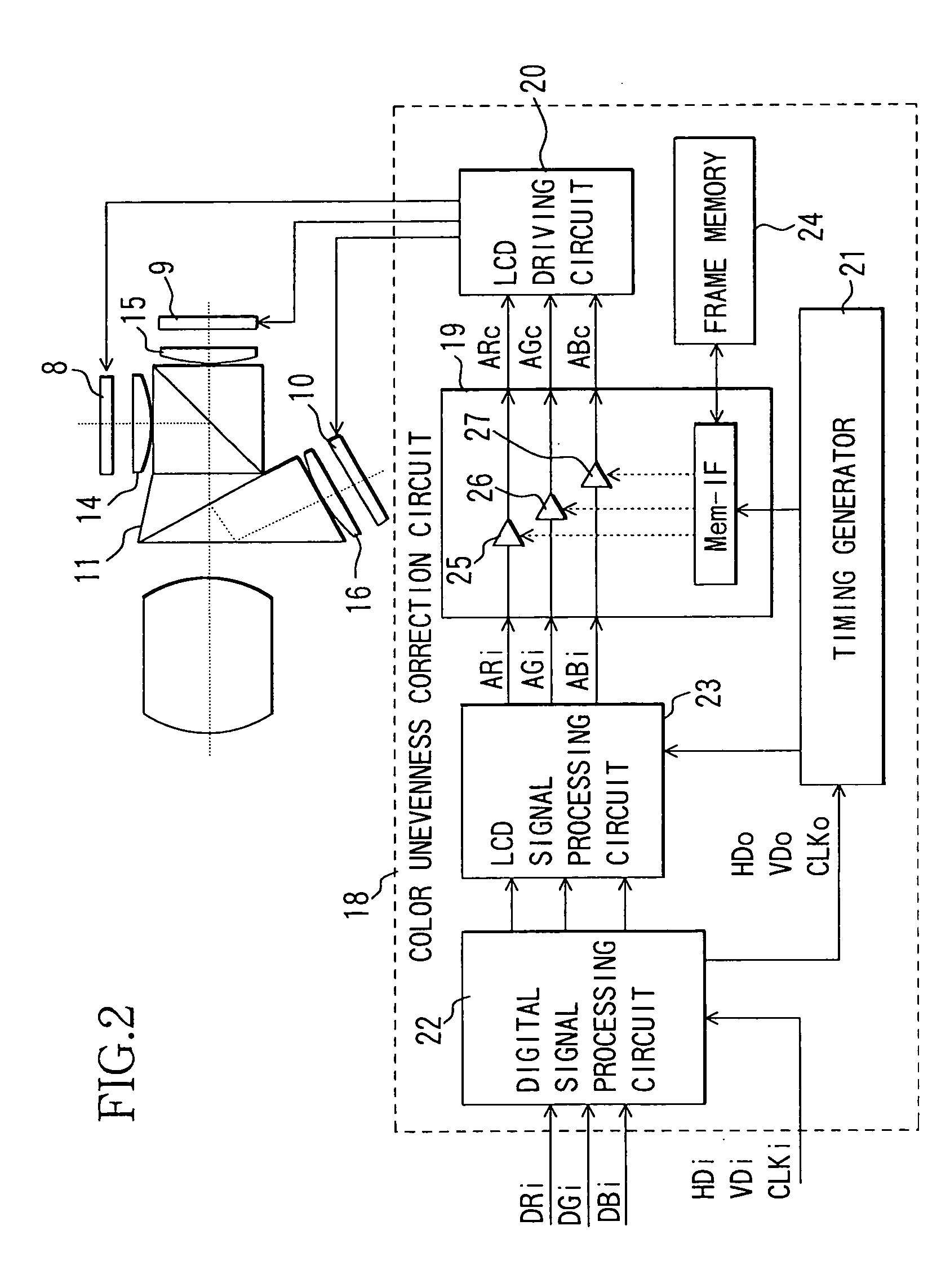
[0027] Light rays that have entered the liquid crystal panels 8, 9 and 10 are then modulated by the liquid crystal panels 8, 9 and 10, respectively, that display images, thereby producing spatially modulated light in accordance with th...


PUM


Abstract

A projection type image display device includes a plurality of image display elements that perform modulation of light rays in accordance with an image signal, a color synthesizing optical element for synthesizing light rays having mutually different wavelength ranges that have been modulated by these image display elements by use of a dichroic membrane, lens groups having a positive refractive power as a whole that are disposed between the image display element and the color synthesizing optical element, and a projection optical system for projecting an image synthesized by the color synthesizing optical element. The projection type image display device further includes a storage circuit for storing data used to correct the brightness irregularity of a projected image, and a brightness irregularity correcting circuit for correcting brightness irregularity of a projected image on the basis of the data stored in the storage circuit.

Description

BACKGROUND OF THE INVENTION [0001] 1. Field of the Invention [0002] The present invention relates to a projection type image display device, such as a liquid crystal projector, including a color synthesizing optical system that uses a dichroic membrane. [0003] 2. Description of the Related Art [0004] Conventionally, various devices have been proposed as a projection type image display device, such as a liquid crystal projector, including a color synthesizing optical system. [0005] A conventional projection type image display device will now be described with reference to FIG. 8. In FIG. 8, white light emitted from a light source 201 is transformed into substantially parallel rays of light by a parabolic mirror 2, a reflecting mirror (not shown), and a lens group (not shown). [0006] The substantially parallel rays of light are subjected to color separation by dichroic mirrors 203 and 204, highly reflecting mirrors 205, 206 and 207, and a lens group (not shown), and are condensed to l...

Claims


Application Information

Patent Timeline
IPC IPC(8): G03B21/00G02F1/13G09G3/20G09G3/34G09G3/36H04N5/202H04N5/57H04N5/74H04N9/31H04N9/68H04N9/69
CPCG09G3/34G09G3/3611G09G2320/0233G09G2320/0242G09G2320/0285H04N2005/745H04N5/57H04N9/3182H04N9/3197H04N9/68H04N9/69H04N5/202
Inventor YOKOYAMA, TOSHIHIKOSUZUKI, YASUO
Owner CANON KK
Why Eureka
Try Eureka