
Device control using job ticket scoring

a device control and job ticket technology, applied in the direction of digital output to print units, instruments, electrographic process apparatuses, etc., can solve the problems of inability to adapt data structures to serve users, lack of interoperability of data structures used in conventional printer control software,

Active Publication Date: 2005-12-13
MICROSOFT TECH LICENSING LLC
View PDF4 Cites 77 Cited by
  • Summary
  • Abstract
  • Description
  • Claims
  • Application Information

AI Technical Summary

Benefits of technology

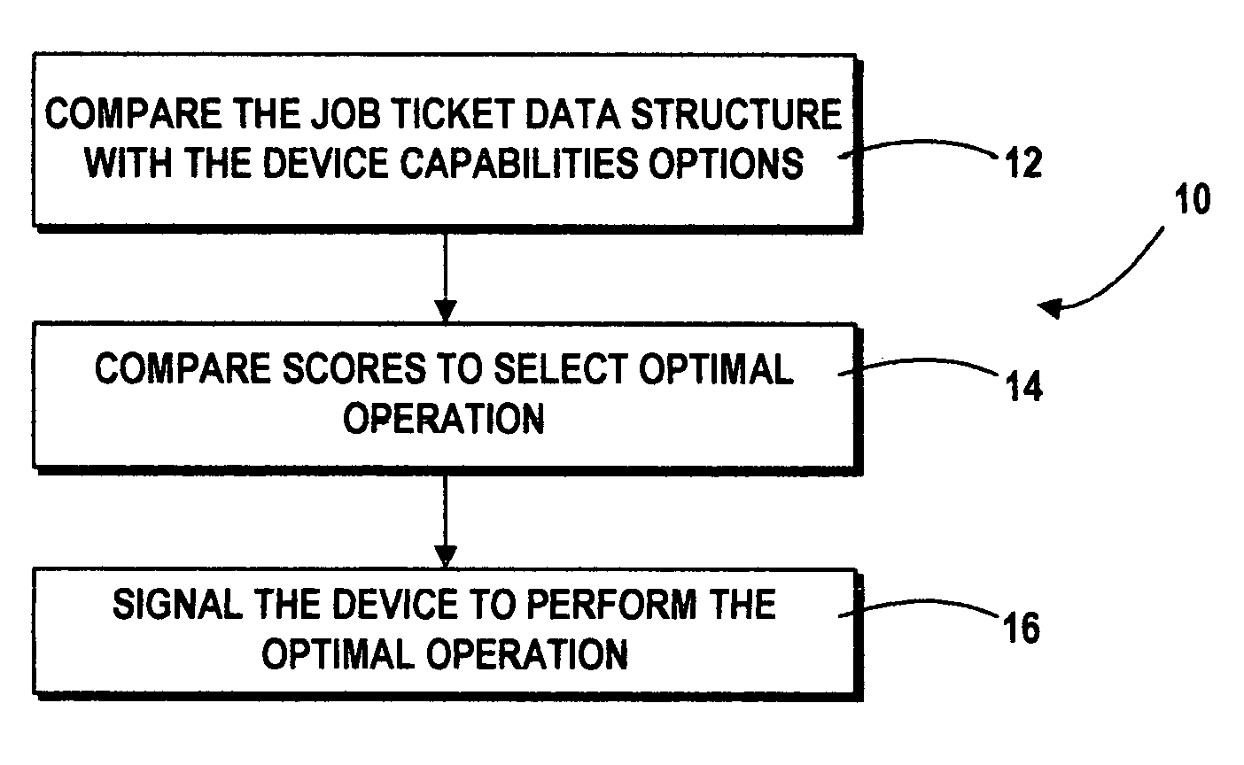
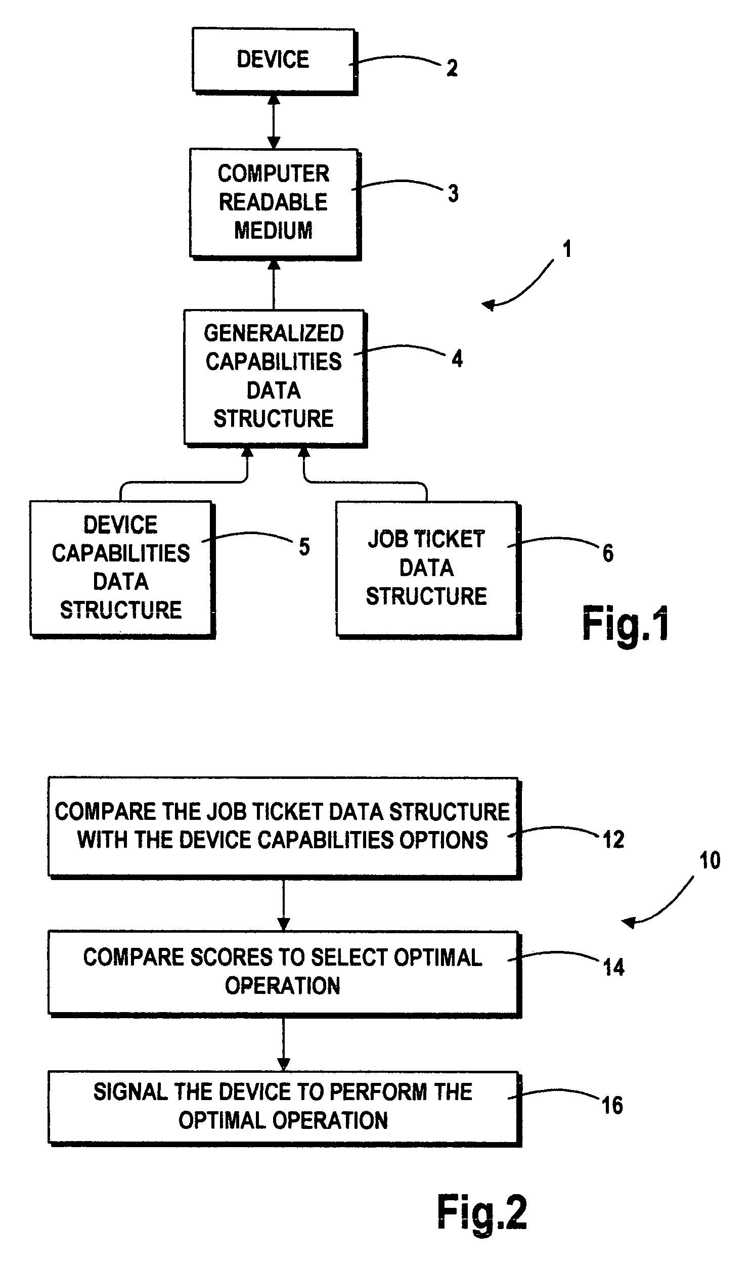
The patent describes a method and system for controlling devices such as printers based on job tickets. The system distinguishes between parameters and features. Each feature contains one or more options, each option containing one or more properties that describe what the device can do when the option is selected. The system calculates a score for each option based on how closely it matches the job ticket. The option with the highest score is considered the optimal operation to perform the job. This method and system improve upon previous techniques by selecting the optimal operation based on the job ticket intent.

Problems solved by technology

The data structures used in conventional printer control software lack interoperability.
Such data structures are not easily adapted to serve users defining similar options using different nomenclature.

Method used


Image

  • Device control using job ticket scoring
  • Device control using job ticket scoring
  • Device control using job ticket scoring

Examples


example 1

[0044]Suppose that a generalized capabilities data structure for a class of electronic printers includes the tree of generalized properties subordinate to the feature “MediaType”140 which is illustrated in FIG. 6. According to this scheme, “MediaType”140 has the following properties:[0045]MediaWeight (142): Light (20 lb.), Medium (24 lb.), Heavy (28 lb.), Ultra Heavy (32 lb.)[0046]Color (144): Transparent, White, Red, Green, Blue[0047]ColorSaturation (146): None, Light, Medium, Intense[0048]Texture (148): Glossy, Bond, ClayCoated[0049]HoleTreatment (150):[0050]LeftEdge (152): None, TwoHoleLeftEdge, ThreeHoleLeftEdge[0051]TopEdge (154): None, TwoHoleTopEdge[0052]PrePrinted (156): Plain, Letterhead, Watermark, Borders

[0053]Consider the following job ticket:[0054]MediaWeight: Medium[0055](Weight=100)[0056](VarianceFactor=5)[0057]Color: White[0058](Weight=100)[0059]ColorSaturation: None[0060](Weight=100)[0061]Texture: Bond[0062](Weight=100)[0063]HoleTreatment:[0064](Weight=200)[0065]Lef...

example 2

[0108]The interoperability of the exemplary system and method will be illustrated by the following example. Assume that an institution has created standard definitions of MediaSize (e.g., paper size) properties. Let the standard MediaSize property contain the following options (expressed in XML code):[0109][0110][0111][0112][0113]

[0114]Now assume that there exist other clients that use another system of referring to media sizes. This system describes media sizes using a different naming convention, which will be referred to as the “A Name” system. Let there be another group of clients that use a second naming convention, which will be referred to as the “B Name” system.

[0115]The exemplary system and method allow devices to accommodate these client's naming conventions by simply adding the “A Name” system and the “B Name” system as additional subproperties for the MediaSize property:[0116][0117][0118][0119][0120][0121][0122]

[0123]Thus, if a client requests a media size by referencing...


PUM


Abstract

A method for controlling a device capable of performing an operation in response to a job ticket includes comparing the job ticket with options within the capabilities of the device for fulfilling the job. One such device is a printer coupled to a computer for printing text and the like in accordance with such a job ticket. The job configuration and the options defining the plurality of operations preferably are stored in data structures, most preferably XML files validated under an XML schema defining options for a universe of similar operations. Each comparison of the job configuration with a device capability option results in a score. These scores are compared to obtain an optimal or preferred option which best approximates the job ticket within the capabilities of the device.

Description

FIELD OF THE INVENTION[0001]The present invention concerns the control of devices such as electronic printers capable of performing operations fulfilled by device capabilities options.BACKGROUND ART[0002]Numerous electronic devices are capable of performing operations fulfilled by options selected by a user. For example, some conventional clothes dryers are configured to allow users to choose from pre-defined drying cycles designed for popular fabric types such as cotton, wool or silk. The choice of cycle controls the time, temperature and degree of agitation used in drying the fabric. If a user wishes to dry a fabric which is not among the particular types for which pre-defined cycles have been provided, the user must choose among those cycles the combination of time, temperature and degree of agitation which best approximates the ideal for the fabric which the user wishes to dry.[0003]This observation is true for many peripheral devices for data processing systems and the like. Co...

Claims


Application Information

Patent Timeline
Patent Type & Authority Patents(United States)
IPC IPC(8): G03G15/00G06F3/12
CPCG06F3/1204G06F3/1232G06F3/1246G06F3/1285
Inventor WONG, PETER W.
Owner MICROSOFT TECH LICENSING LLC
Learn More