Coaxial connector

a technology of coaxial connectors and connectors, which is applied in the direction of electrically conductive connections, coupling device connections, electrical apparatus, etc., can solve the problems of o-rings and cable bushings or other rubber parts being unable to cover the entire tolerance range of the respective outer conductors of the cabl

Inactive Publication Date: 2005-12-20
SPINNER
View PDF10 Cites 55 Cited by
  • Summary
  • Abstract
  • Description
  • Claims
  • Application Information

AI Technical Summary

Problems solved by technology

O-rings and cable bushings or other shaped rubber parts have the disadvantage of being unable to cover the entire tolerance range of the respective outer conductors of the cable.
Moreover, deformations, and especially subsequent deformations of the outer conductor of the cable in the region of the transition into the connector, will inevitably lead to leakiness.
Sealing by means of shrinkdown plastic tubing comes with the disadvantage that at the frequently exposed mounting locations it is necessary to work with hot air.

Method used


Image

  • Coaxial connector
  • Coaxial connector
  • Coaxial connector

Examples


second embodiment

[0034]FIGS. 3 and 4 illustrate the connector which is especially intended for mounting on a coaxial cable with a ring-wave outer cable conductor 4. With the exception of the differences explained below, the connector is similar to the connector described, above, with respect to FIGS. 1 and 2. The connector comprises a sleeve 9.2 which receives an elastic perimeter seal 11 in a form-fitting manner, with the ring-shaped lip 11a of the seal having an inside diameter in the unloaded state which is smaller than the smallest diameter of the outer cable conductor 4 in the region of the wave trough. At the same time, the inside diameter of the sleeve 9.2 is dimensioned in such a way that the lip 11a has a sufficient radial width which allows it to yield in the direction of the plug side for example when the connector is slid onto the coaxial cable. The positioning of the perimeter seal 11 within the sleeve 9.2 and thus also relating to the base of the recess 7a of the connector head 7 is ch...

third embodiment

[0038]FIG. 8 finally shows an embodiment of the connector in which the sleeve-like perimeter seal 12 is arranged as in the third embodiment according to FIGS. 5 and 6, i.e. it only comprises the two lips 12a and 12b. For the purpose of axial and thus also radial compression of the outer sealing lip 12b a cap nut 22 is additionally screwed onto sleeve 9.1.


PUM


Abstract

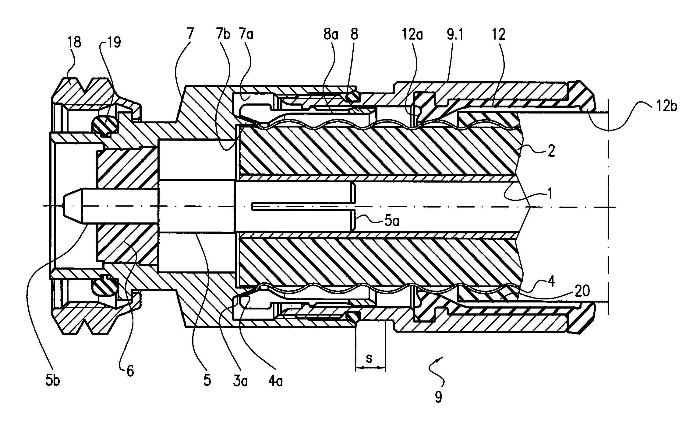
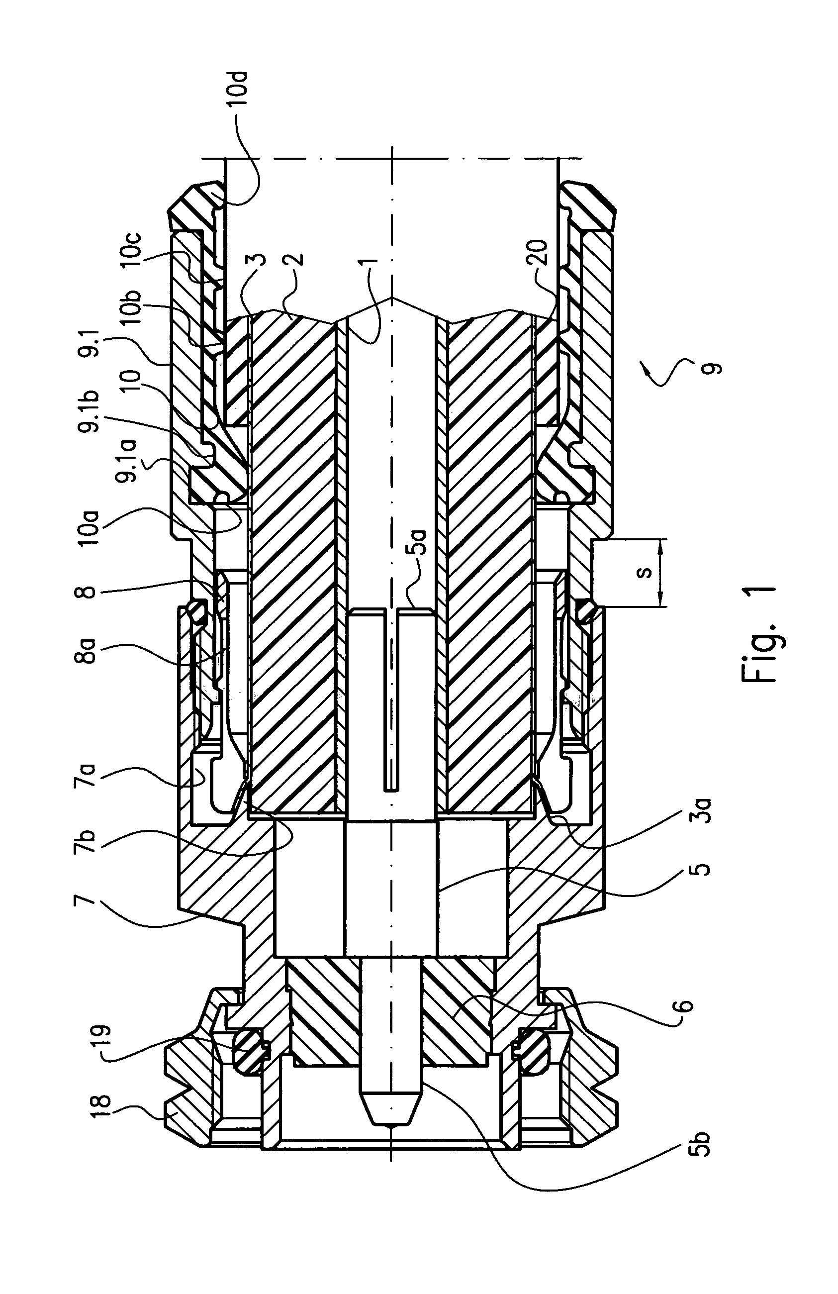
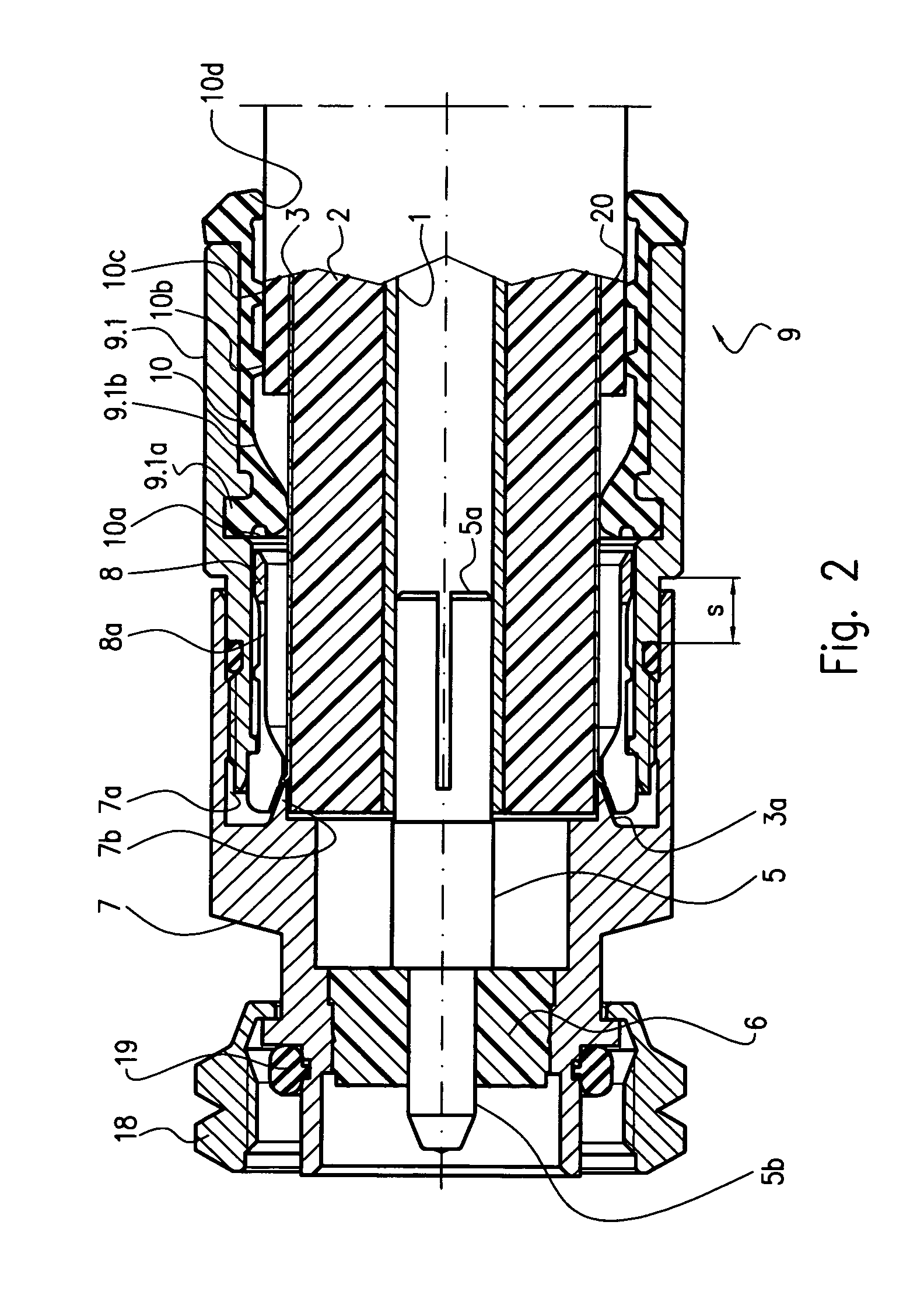
In a coaxial connector, especially an integrally pre-mounted connector, the recess (7a) receiving the end of the coaxial cable can be sealed in the connector head (7) relative to the cable with the help of an integrated perimeter seal (10). For this purpose the perimeter seal (10) is received in a form-fitting manner in a pressure member (9) which establishes the electric connection between the outer cable conductor (3) and the conductor head (7) and connects the same in a manner so as to be secure against withdrawal. The perimeter seal comprises at least one and preferably several ring-like lips (10a, 10b, 10c) which project radially inwardly, deform when the pressure member (9) is slid onto the cable in the direction of its end (3a) and, after the clamping of the pressure member, stand again in the same radial plane as in the unloaded state.

Description

BACKGROUND OF THE INVENTION[0001]1. Field of the Invention[0002]The invention relates to a coaxial connector with a connector head comprising a recess for receiving the end of a coaxial cable and a cable clamp which comprises at least one pressure member which encompasses the coaxial cable, can be clamped with the connector head and, after clamping with the connector head, establishes electric contact between at least the outer conductor of the cable and the connector head and joins them mechanically in a manner so as to be secure from withdrawal, with the recess in the connector head being sealed relative to the cable.[0003]2. Description of the Related Art[0004]Such connectors intended for mounting at the end of a coaxial cable are known in arrangements comprising several parts to be mounted and, according to the current state of the art, in arrangements where they are pre-mounted in an integral design (cf. DE 197 34 236 C2, DE 197 38 733 C1, DE 198 57 528 C2 and EP 1 028 498 A1)....

Claims


Application Information

Patent Timeline
Patent Type & Authority Patents(United States)
IPC IPC(8): H01R13/52H01R13/646
CPCH01R13/5205H01R24/564H01R2103/00
Inventor WILD, WERNERBINDER, THOMAS
Owner SPINNER
Why Eureka
Try Eureka