
Reed switch apparatus

a technology of reed switches and switches, applied in the field of reed switches, can solve the problems of reed switches, fragile nature, circuits to be completed or broken, etc., and achieve the effect of facilitating communication

Inactive Publication Date: 2005-12-20
GILMORE GLENDELL N
View PDF25 Cites 14 Cited by
  • Summary
  • Abstract
  • Description
  • Claims
  • Application Information

AI Technical Summary

Benefits of technology

[0011]The present invention also includes as another embodiment a method of controlling a plurality of devices with a reed switch apparatus having a plurality of reed switches. When the reed switch apparatus is exposed to a single magnetic field, the plurality of reed switches are activated. The activation of the plurality of reed switches facilitates the communication with each of the plurality of devices. Yet another embodiment of the invention includes a method of activating a device via the use of a single reed switch mounted to a portion of a warehouse structure.

Problems solved by technology

For example, a reed switch can cause a circuit to be completed or broken when a window or door opens or closes.
Reed switches are by their very nature fragile—that is, the glass capsules can break.
An exacerbation of the fragile nature is the likelihood that two reed switches may be in too close of proximity to one another, hitting and breaking each other.

Method used


Image

  • Reed switch apparatus
  • Reed switch apparatus
  • Reed switch apparatus

Examples


Embodiment Construction

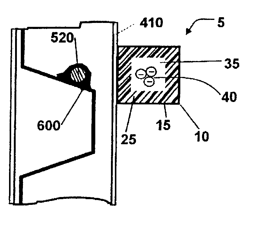
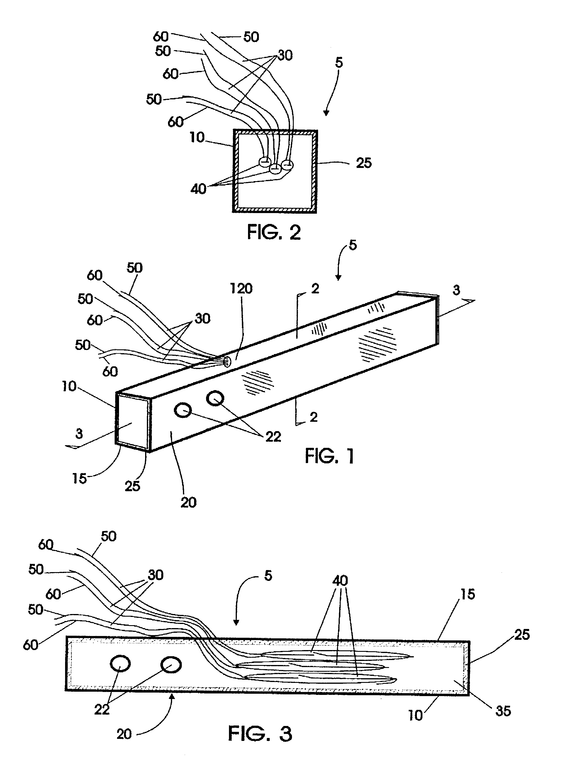
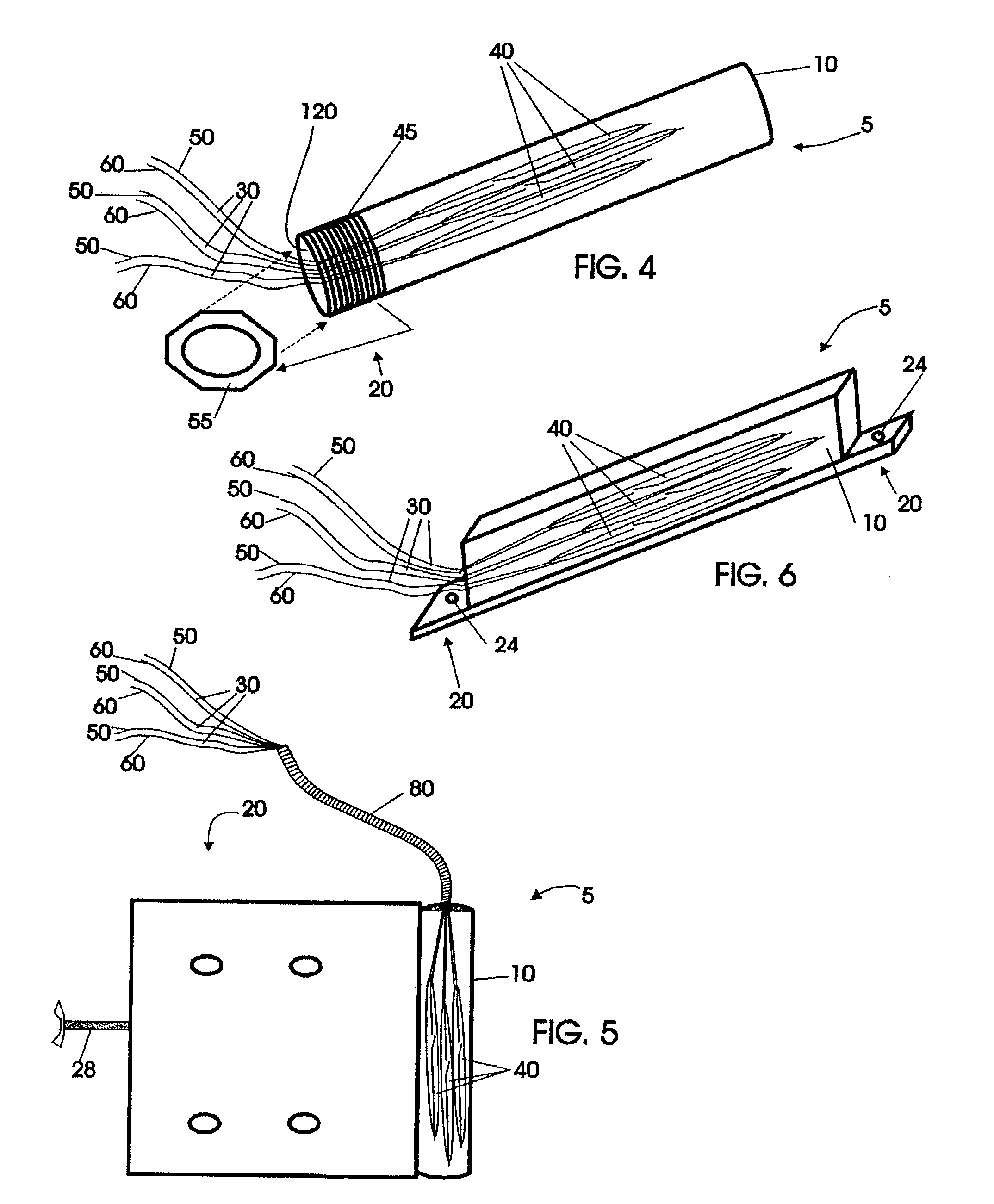
[0028]Several different embodiments, not drawn to scale, are shown in FIGS. 1–14, illustrating several concepts of the invention. FIGS. 1–3, in several views show a first embodiment of a reed switch apparatus 5. The reed switch apparatus 5 in this embodiment includes a reed switch housing 10, a plurality of reed switches 40 (FIG. 3) and a attachment device 20. The reed switch housing 10 includes an outer body 15, which is arranged and designed as an outermost protective coating for the reed switches 40. The choice of material for outer body 15 can vary with design and intended use, but preferably the material is of such a nature that it is non-magnetic—or, will not interfere with the magnetic action of reed switches—and is strong and rigid enough to maintain its position when mounted to a specific object, e.g., a door or window. Suitable material for outer body 15 would include aluminum and plastic. The outer body 15 of the reed switch housing 10 can be of such a nature that it will...


PUM


Abstract

A reed switch apparatus utilizes one or more reed switches to communicate with one or more devices. In one configuration, the reed switch apparatus utilizes a single magnetic field to simultaneously activate two or more reed switches. In another configuration, two or more reed switches, each acting independent of one another are simultaneously activated by a single magnetic field. Additionally, a method of controlling at least two devices includes exposing a reed switch apparatus to a single magnetic field. Yet another method includes a activating a device via the use of a single reed switch mounted to a portion of a warehouse structure.

Description

CROSS-REFERENCE TO RELATED APPLICATIONS[0001]Not Applicable.STATEMENTS REGARDING FEDERALLY SPONSORED RESEARCH OR DEVELOPMENT[0002]Not applicable.REFERENCE TO A MICROFICHE APPENDIX[0003]Not applicable.BACKGROUND OF THE INVENTION[0004]1. Field of the Invention[0005]The present invention relates generally to reed switches and more specifically to the use of one or more reed switches to control one or more devices[0006]2. Description of the Related Art[0007]Reed switches are magnetically operated switches, which are generally formed by a pair of spaced ferromagnetic contacts or blades, hermetically sealed in a glass capsule. In a typical application and use of a reed switch, the blades are connected to outside leads—each outside lead being part of a circuit. The exposure of the blades to a magnetic field—coming from either a permanent magnetic or electromagnetic generation—forces the blades to move, either contacting one another or moving a way from one another. In what is known as a no...

Claims


Application Information

Patent Timeline
IPC IPC(8): H01H36/00
CPCH01H36/0006
Inventor GILMORE, GLENDELL N.
Owner GILMORE GLENDELL N
Learn More