Apparatus for rotating an article

a technology for rotating objects and articles, applied in the direction of conveyor parts, rolling carriages, transportation and packaging, etc., can solve the problems of likewise having to be adapted, and achieve the effect of reducing the force which is necessary for rotation, convenient and cost-effective production, and efficient transportation

Inactive Publication Date: 2006-01-03
ROBERT BOSCH GMBH
View PDF22 Cites 27 Cited by
  • Summary
  • Abstract
  • Description
  • Claims
  • Application Information

AI Technical Summary

Benefits of technology

[0013]Since the articles merely have to be positioned on the conveyors, and there is no need for any further rotary means adapted specifically to the shape and size of the articles, the apparatus can be used for different articles without any changes in design. Since the articles do not have to be clamped in-between mounts, it is possible for difficult articles to be reliably transported and rotated. In addition, the force which is necessary for rotation is minimized.
[0014]It is further advantageous that the apparatus requires only a relatively small number of elements and is thus straightforward and cost-effective to produce.
[0015]Using the same means, the articles can be both transported efficiently along a path and also rotated simultaneously, with sufficient positional accuracy, about an axis perpendicular to the transporting plane. This allows low-friction rotation. In addition, the time taken to transport the article is not delayed by its rotation.
[0016]The efficiency of the transporting and / or of the rotation operation may additionally be increased by at least two of the conveyors being driven, with the result that, in addition to the difference in speed which is necessary for the rotary movement, there is a common speed component which transports the article forward as it is rotated. The conveyors thus serve as longitudinal conveyors and as rotary conveyors.
[0021]The positional accuracy can be increased by aligning means which are arranged downstream of the longitudinal and rotary conveyors in the transporting direction. Such aligning means are, for example, lateral guides and / or separately driven and moveable stopper elements.

Problems solved by technology

These apparatuses have the disadvantage that they have to be adapted to the shape and size of the articles which are to be transported.
These apparatuses mentioned above all have the disadvantage that they likewise have to be adapted to the respective size and shape of the articles.

Method used


Image

  • Apparatus for rotating an article
  • Apparatus for rotating an article
  • Apparatus for rotating an article

Examples


first embodiment

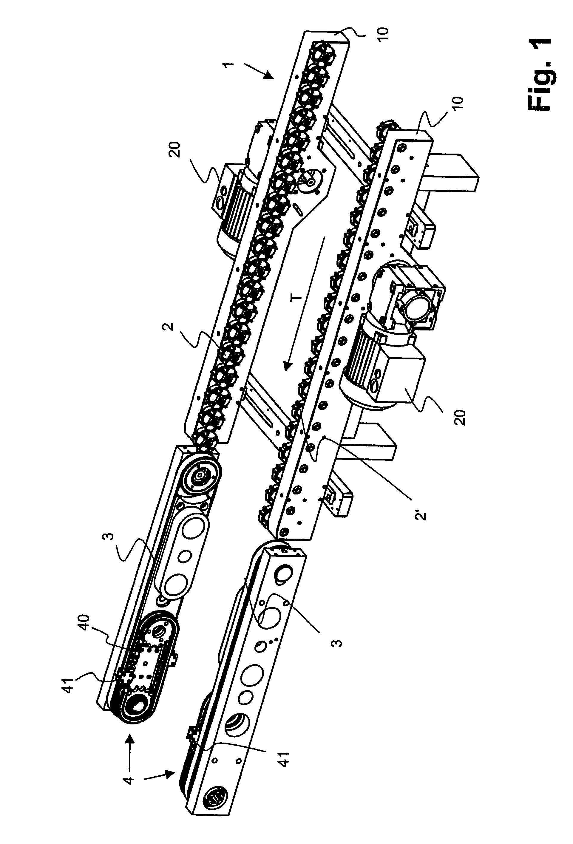
[0024]FIG. 1 shows a perspective view of the apparatus according to the invention;

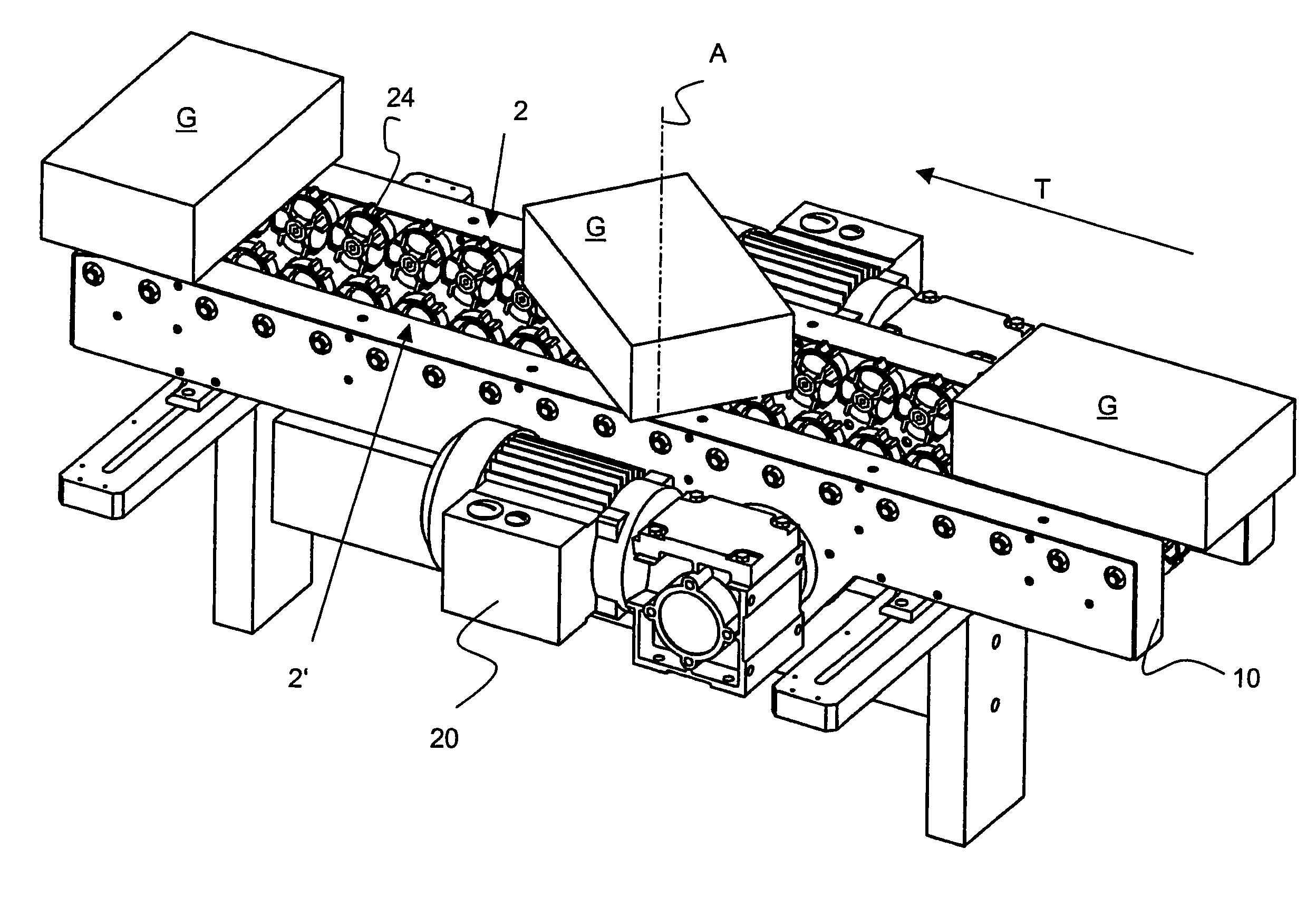
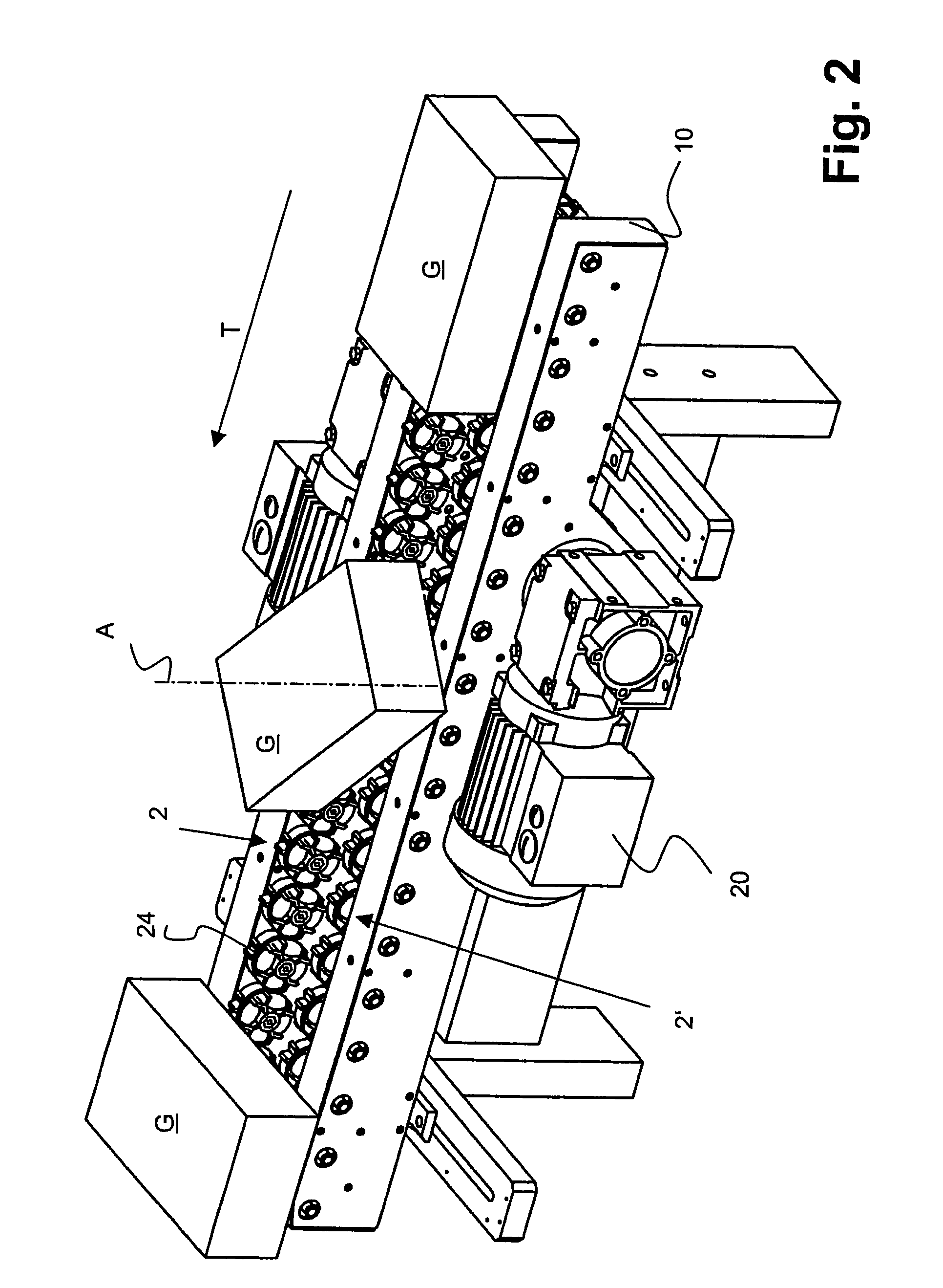
[0025]FIG. 2 shows a detail of the apparatus according to FIG. 1 with boxes arranged thereon;

[0026]FIG. 3 shows a perspective view of part of the apparatus according to FIG. 1 with omnidirectional rollers and a drive illustrated;

[0027]FIG. 4a shows a perspective view of an omnidirectional roller;

[0028]FIG. 4b shows a view of the omnidirectional roller according to FIG. 4a from above;

[0029]FIG. 4c shows a side view of the omnidirectional roller according to FIG. 4a;

second embodiment

[0030]FIG. 5 shows a perspective view of the apparatus according to the invention; and

third embodiment

[0031]FIG. 6 shows a perspective view of the essential parts of the apparatus according to the invention.

METHODS OF IMPLEMENTING THE INVENTION

[0032]FIG. 1 illustrates a first exemplary embodiment of the apparatus according to the invention. Two longitudinal and rotary conveyors 2, 2′ are arranged on two spaced-apart side panels 10 of a framework 1. These longitudinal and rotary conveyers 2, 2′ extend along a transporting direction T which is illustrated by an arrow. The corresponding rotary and transporting planes for the articles G which are to be transported and rotated, and are illustrated in FIG. 2, thus preferably run horizontally.

[0033]The longitudinal and rotary conveyors 2, 2′ are followed by a horizontal conveyor 3. The latter may be arranged on the same or a different framework 1. An aligning means, in this case a stopping means 4, is preferably provided in the region of the horizontal conveyor 3.

[0034]In the example illustrated here, each of the longitudinal and rotary co...


PUM


Abstract

An apparatus having approximately parallel conveyors (2, 2′) for transporting and rotating an article (G) has multiple longitudinally arranged omnidirectional rollers (24), each omnidirectional roller (24) having multiple individual rollers (240) arranged about its periphery. The conveyors (2, 2′) extend in a transporting direction (T), bear against the bottom of the article (G), and rotate the article about an axis perpendicular to the article bearing plane. At least one conveyor can be driven at a speed different from the other conveyor to transport and rotate the article on the conveyor. The bearing portion of article (G) is subject to direction-dependent coefficients of friction with the transporting direction (T) having a static or sliding coefficient of friction that is higher than the rolling coefficient of friction in the direction perpendicular (S) to the transporting direction (T).

Description

TECHNICAL FIELD[0001]The invention relates to an apparatus for rotating an article. The apparatus is suitable, in particular, for transporting and rotating containers, for example boxes.PRIOR ART[0002]DE-A-39,15,246 discloses an apparatus which is intended for conveying articles and in which the articles are rotated in a controlled manner about an axis perpendicular to the conveying path as they are conveyed. Rotatable carriers, on which the articles which are to be rotated are arranged, are provided for this purpose.[0003]DE-A-199,48,704 uses a turntable in order to rotate stacks of paper as they are transported.[0004]EP-A-0,472,984 discloses a conveying and rotating apparatus with two conveying belts arranged one above the other. A round article which is to be rotated is transported on the bottom conveying belt which is provided with carry-along elements. Provided on the top conveying belt are downwardly projecting guide tracks which retain the article in position. Also provided a...

Claims


Application Information

Patent Timeline
Patent Type & Authority Patents(United States)
IPC IPC(8): B65G47/24B65G13/02B65G47/244
CPCB65G47/2445B65G13/02
Inventor MEYER, PETER
Owner ROBERT BOSCH GMBH
Why Eureka
Try Eureka