
Extendable and angularly adjustable handle for wheeled luggage

a technology of angular adjustment and wheeled luggage, which is applied in the field of cases or luggage, can solve the problems of unalleviated problems and disadvantages, potentially damaged fixed inclined handles, and limited guiding means, so as to achieve the effect of optimizing the towing position

Inactive Publication Date: 2006-07-04
OUTRIGGER
View PDF19 Cites 38 Cited by
  • Summary
  • Abstract
  • Description
  • Claims
  • Application Information

AI Technical Summary

Benefits of technology

[0015]A second embodiment of the invention dispenses with the spring-loading of the hinge, thereby allowing the user to manually rotate the handle to a desired or predetermined inclined position.
[0018]In order to prepare for towing, the user tilts the top of the luggage without causing it to roll on the wheels. This step is preferably done with extending the handle. When the luggage reaches the balanced position with the center of gravity over the axis of rotation of the wheel, there will be no tendency of the luggage to continue to tilt forward or to return to the vertical or rest position. When the luggage reaches this balanced position, the user notes the position of the tilt gauge indicator, being either the bubble or tip of the swing arm, relative to the stationary indicia. With this balanced point indicia in mind, the user then sets the angular position of the handle, thereby fixing the position of the handle grip to minimize the vertical force required to maintain the luggage during towing. This method and apparatus is adapted for use with luggage and cases of all sizes to assist the user in optimizing the angularly adjustable hand.
[0019]What I have found in the course of various experiments and tests with prototype constructions embodying my invention, is that a relatively narrow range of angular displacement, e.g., from the vertical, will allow a large majority of users to comfortably tow different sizes of wheeled luggage. This finding applies to a group of users whose height varied considerably from about five feet to well over six feet. This is a surprising finding, since it has long been assumed that the reasonably comfortable hand position for a tall user who was well above the mean or average male height of 5′-9″, would be significantly different that a shorter use of a height well below the mean height. Thus, what I have discovered is that for users within a broad range of heights, that when the hand is extended rearwardly in the towing position, the vertical distance between the hand and the floor are substantially the same. From this determination, I have found that there are a limited range of angular displacement which creates a greatly improved, if not optimum center of gravity position that maximizes comfort and minimizes effort and strain during towing. This finding applies to luggage that is packed; luggage packed and supporting another piece on the top; or luggage packed and carrying an accessory on a strap that shifts the weight to the vertical wall opposite the extendable handle.

Problems solved by technology

It has been found that a fixed inclined handle is potentially subject to damage, i.e., bending or possibly even breaking if the case falls on the extended end of the handle, my U.S. Pat. No. 6,129,365 generally discloses several embodiments of a handle designed to resist such bending or breakage.
Despite their obvious advantages, problems and disadvantages are left unalleviated by the improved disclosed in these two patents.
First, since the guiding means for the handle is disposed at the same angle as the angle which the handle makes with the rear wall of the case, the length of the guiding means is limited by the angle which it makes with the rear wall of the case and the distance between the rear wall and the front wall of the case, if it is assumed that the guiding means is contained within the case.
This may limit the length of the inclined handle which can be contained within the guiding means, and if such length is too short, use of a telescoping inclined handle may be necessary.
Regardless of the height of the handle above the towing surface, this will be a very uncomfortable position for all users during towing because the luggage will be impacting the back of the user's heels, or very nearly so, during a normal pace.

Method used


Image

  • Extendable and angularly adjustable handle for wheeled luggage
  • Extendable and angularly adjustable handle for wheeled luggage
  • Extendable and angularly adjustable handle for wheeled luggage

Examples


Embodiment Construction

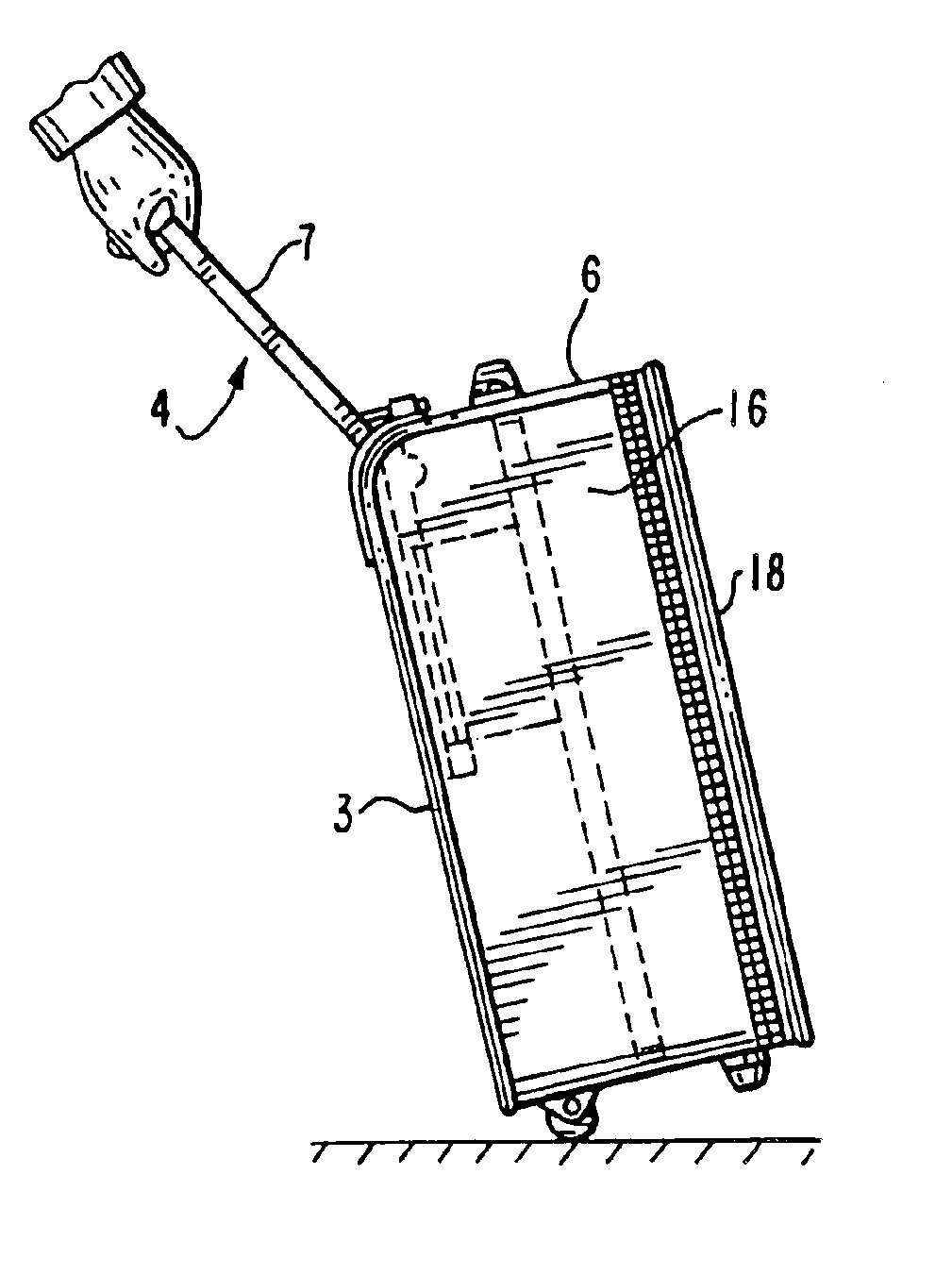
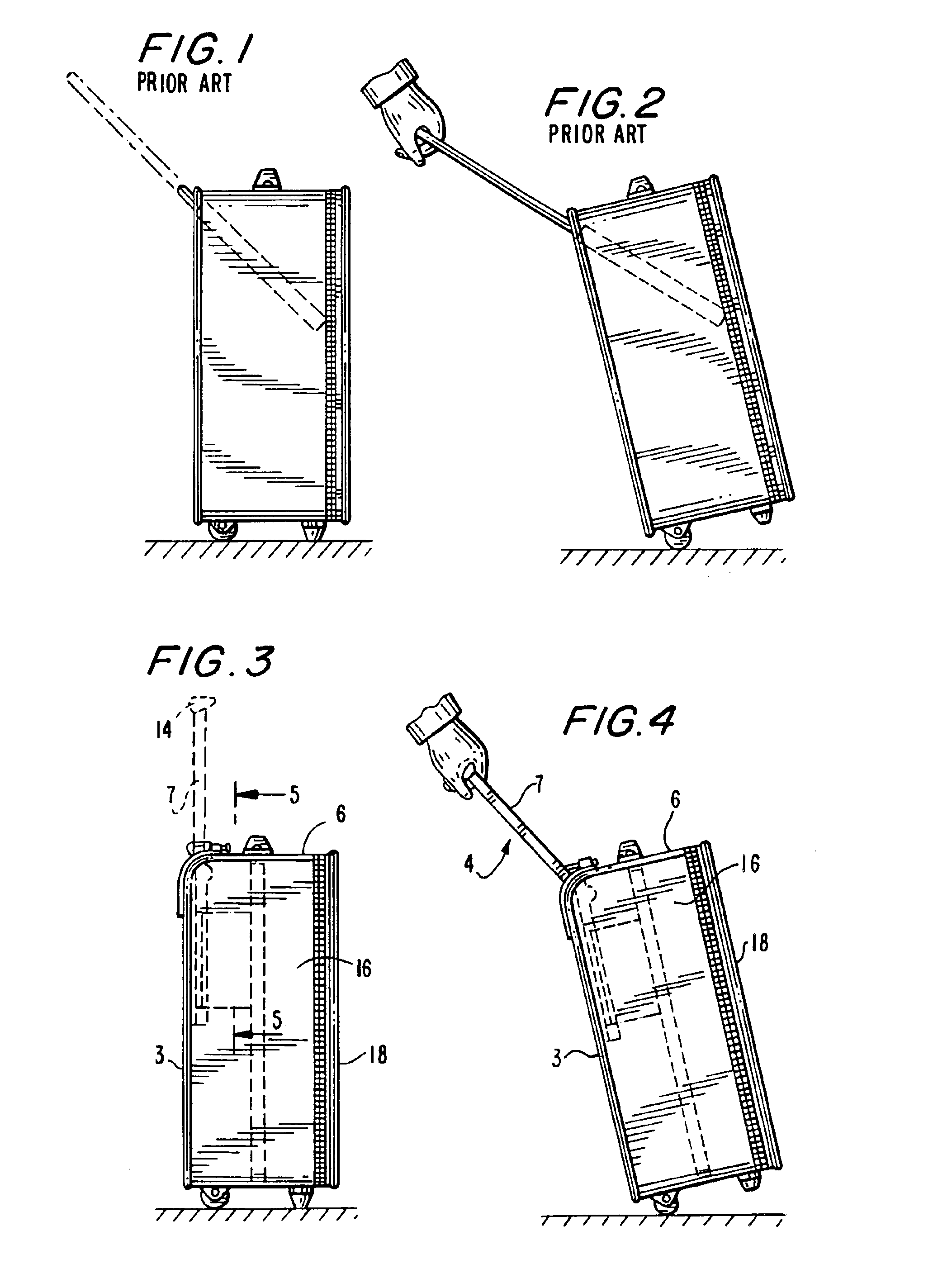
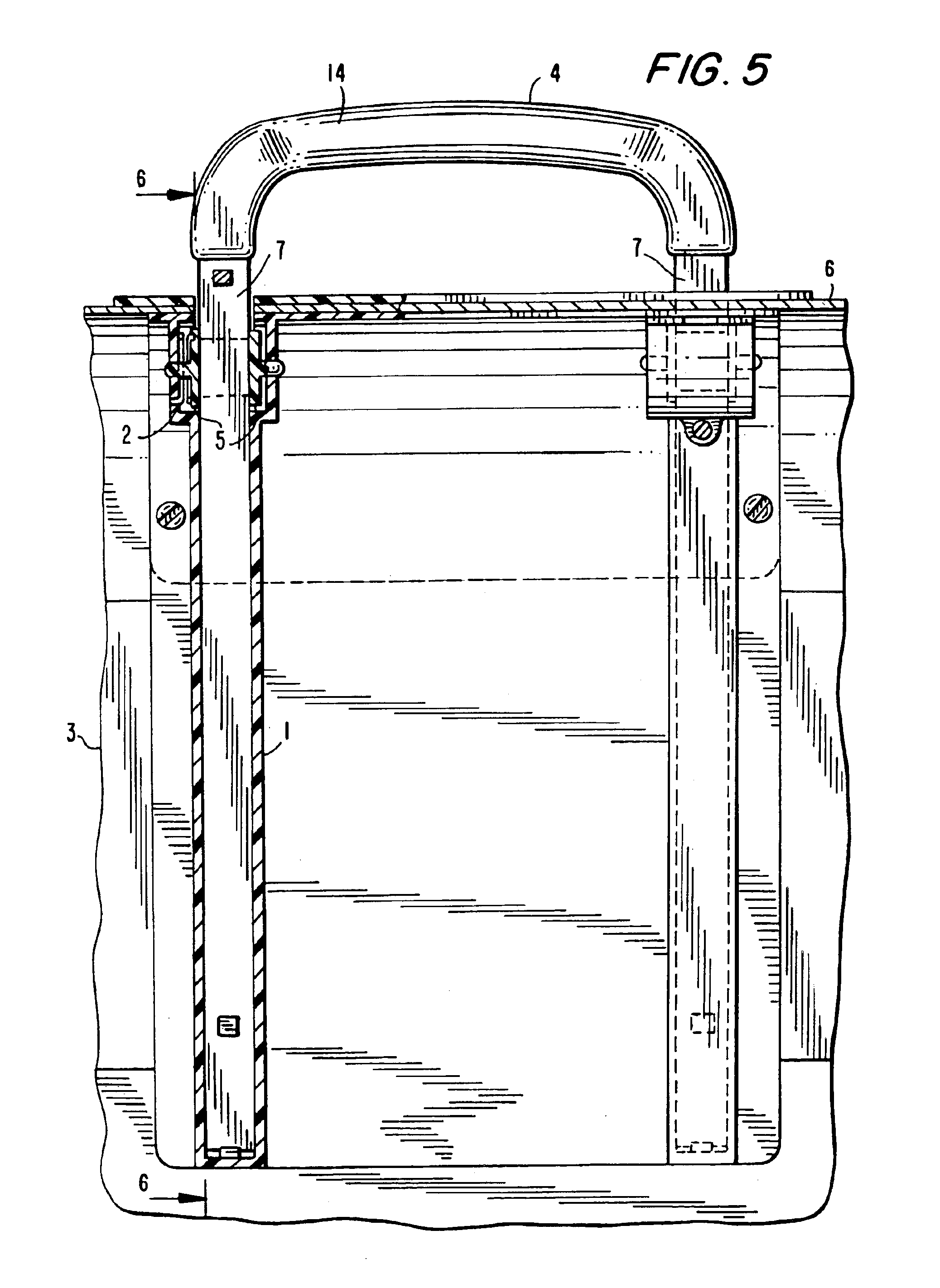
[0071]With reference to FIGS. 1 and 2, there is illustrated a typical wheeled case of the prior art that has been provided with an extendable handle that is inclined at a fixed angle to the front wall of the luggage. In the stowed or retracted position, the arms of the extendable handle are retained in a pair of tubes 1 secured to the interior of the opposing side walls, the hand grip 14 being positioned proximate the junction of the top and back walls. As will be seen from FIG. 2, when extended for towing the handle assembly 4 is withdrawn from storage tubes 1 and the case or luggage is tipped over onto the wheels or rollers 2 for towing. As will be understood, the relative height of the user will determine the most convenient distance of the handle grip above the towing surface which in turn will determine the position of the centered gravity of the luggage relative to the access of rotation of the wheels. As will be understood by one of ordinary skill in the art, the optimum towi...


PUM


Abstract

A wheeled luggage case that is tilted for towing is provided with a retractable and, optionally, telescoping handle (4) assembly that is withdrawn from the interior of the case to an extended vertical position at the intersection of the top and rear walls, from which it is angularly rotated by the user to a position that minimizes the vertical force that is required to support the hand grip to comfortably tow the luggage. Preferred angular displacements for a wide range of users and loads positioned in and on the luggage case have been found to be at about 17° and 35° from the vertical position.

Description

[0001]This application is a provisional application on Ser. No. 60 / 245,393, filed Nov. 2, 2000, and Ser. No. 60 / 260,802 filed Jan. 9, 2001.FIELD OF THE INVENTION[0002]This invention relates to a case or luggage having an extendable handle that may be wheeled in any one of the four directions parallel to the front, rear, and two side walls of the case or luggage and, in particular, to adjustable handles attached to such luggage to effect such wheeling.DESCRIPTION OF THE RELATED ART[0003]The entire disclosures of my U.S. Pat. Nos. 5,868,406 and 6,129,365 are hereby incorporated herein by reference. U.S. Pat. No. 5,868,406 generally discloses a handle inclined at an angle to the rear wall of the case when the handle was extended with respect to the case and when it was retracted with respect to the case. The handle in the retracted state was received in a housing mounted on the case for guiding and supporting the handle at the same angle fixed with respect to the rear wall of the case ...

Claims


Application Information

Patent Timeline
Patent Type & Authority Patents(United States)
IPC IPC(8): B62K15/00A45C5/06A45C5/14A45C7/00A45C13/26A45C13/30
CPCA45C7/0045A45C13/262A45C5/06A45C5/14Y10T16/44A45C13/30A45C2013/267A45C2013/306
Inventor SADOW, BERNARD D.
Owner OUTRIGGER
Learn More