Bistable magnetic drive for a switch

a technology of magnetic drive and solenoid actuator, which is applied in the direction of electrical equipment, high-tension/heavy-duty switches, and electric motors. it can solve the problems of inability to achieve stable intermediate positions between the two end positions of the armature, inability to open or close the switch, and only at a relatively large energy expenditure. it can reduce the force and power, increase the operating reliability, and minimize manufacturing costs. the effect of cos

Inactive Publication Date: 2010-11-30
E I B
View PDF14 Cites 37 Cited by
  • Summary
  • Abstract
  • Description
  • Claims
  • Application Information

AI Technical Summary

Benefits of technology

[0010]Thus, the object of the present invention is to improve upon a magnetic drive of the type described hereinabove in such a way as to minimize the force and power that must be expended in shutdown of the power circuit breaker operated with the drive and thus increase operating reliability on the whole, in particular to the extent that an emergency cutoff can be accomplished as rapidly and as reliably as possible. At the same time, the technical design of the drive should be as simple as possible with regard to its production to ultimately minimize manufacturing costs. In addition to these requirements, however, the use of a shunt body of the type defined in the preamble with the special advantage of a lower force expended in movement of the armature should not be omitted.
[0011]The object is achieved with a magnetic drive of the type defined above according to the present invention by providing a lock for the shunt body by means of which the shunt body can be held in the end position facing it and can be released from this end position with little expenditure of force or power. With this lock, the shunt body can be brought together with the armature relatively rapidly and with little expenditure of force or power in a shutdown operation, in particular in the case of an emergency cutoff of the electric switch that has been operated.
[0012]According to the present invention, the shunt body is used to advantage in cutting off the switch. For the break time, the rate of movement of the shunt body in particular is the deciding factor. However, this requirement is taken into account precisely through the proposed mechanical holding device due to the fact that the shunt body can be released from its holding position with little expenditure of force or power and therefore also relatively rapidly.
[0013]According to a first embodiment of the present invention, the strict safety requirements for trouble-free functioning of a cutoff of a switch operated with the magnetic drive according to the present invention, in particular in the case of an emergency cutoff, are met by the fact that the shunt body can be locked in the end position by means of mechanical holding means. The proposed mechanical holding means for the shunt body is less susceptible to trouble in comparison with electric or magnetic holding devices, for example, and furthermore, it is still fully functional in an emergency situation, which is often associated with a power outage.
[0016]As an alternative, a mechanical threshold or barrier by means of which the shunt body is held detachably in the end position facing the shunt body by a slight holding force may be provided so that the shunt body can be released from this end position by overcoming this low force potential and can be brought together with the armature.

Problems solved by technology

Despite the relatively low opening energy, no stable intermediate position between the two end positions of the armature is possible, i.e., once a switching operation has been initiated, it necessarily leads to opening or closing of the switch.
Therefore, technically complicated additional mechanical devices (e.g., lever devices) must be provided with the known switches, so that the armature can be moved into the “OFF” position of the switch, and meanwhile the cutoff can be accomplished only at a relatively great expenditure of energy.

Method used


Image

  • Bistable magnetic drive for a switch
  • Bistable magnetic drive for a switch
  • Bistable magnetic drive for a switch

Examples


Embodiment Construction

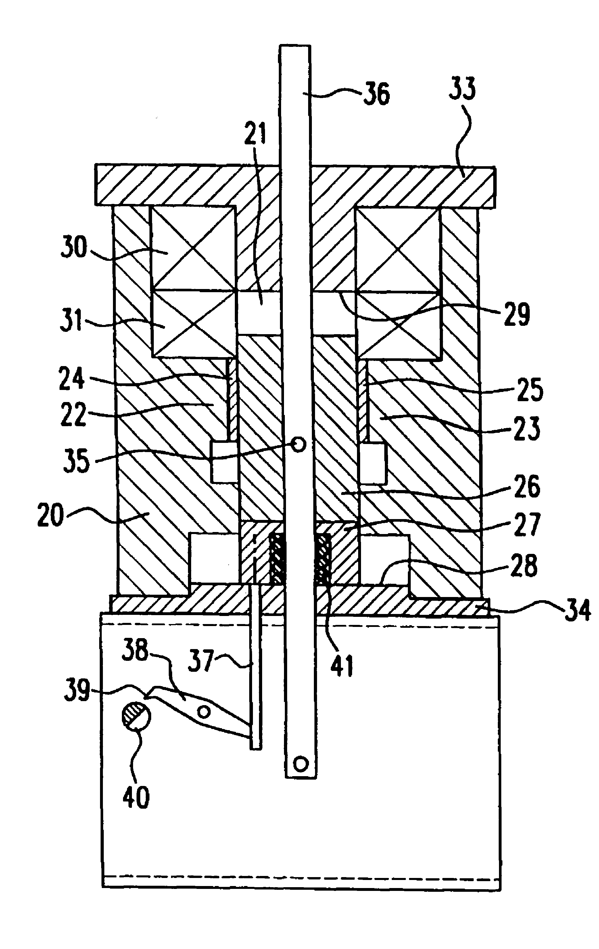
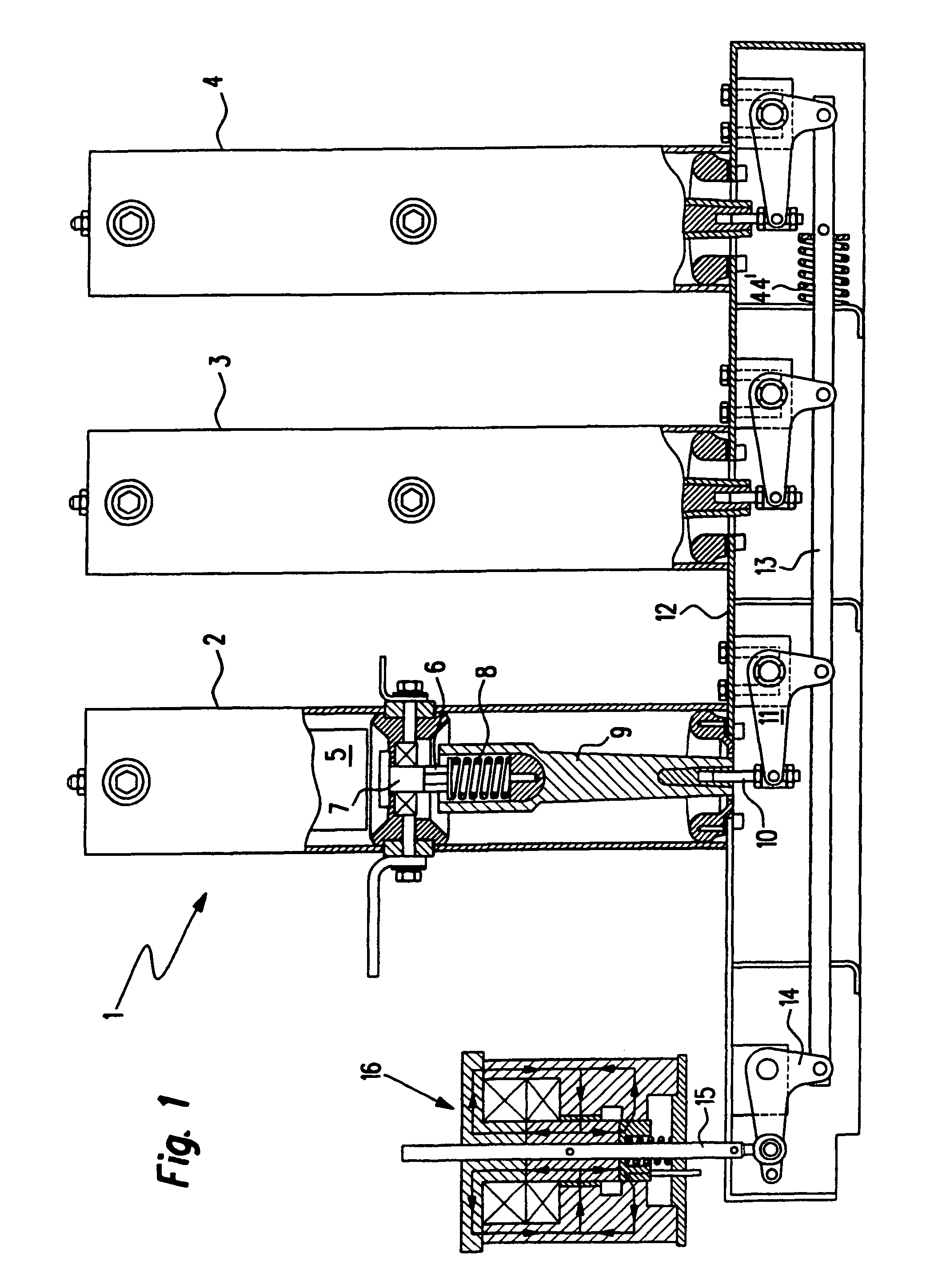
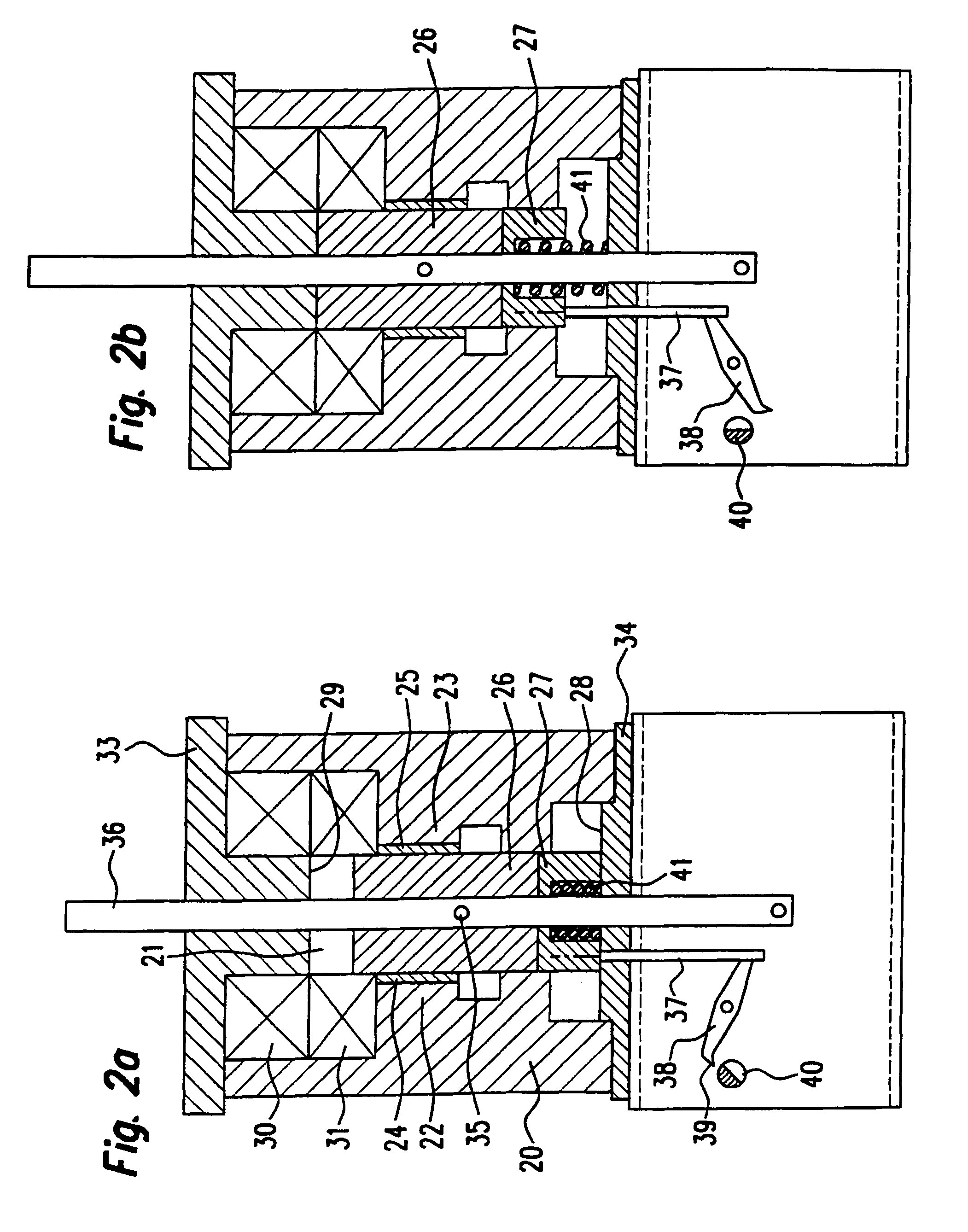
[0025]With reference to FIG. 1, first the use of a magnetic drive according to the present invention is described in the case of a medium- or high-voltage power circuit breaker. A power circuit breaker 1 contains three switch poles 2, 3, 4, each having an interrupter chamber 5 containing a stationary switch contact (not shown in detail) and a mobile switch contact (also not shown). Interrupter chamber 5, e.g., a vacuum interrupter, is of a traditional design. The movable switch contact is connected to an axle 7 which is mounted so that it can be displaced along a shaft 6 under the prestress of a spring 8. In the on or closed position of the power circuit breaker, springs 8 of switch poles 2, 3, 4 are stretched, i.e., the springs relax on opening of the power circuit breaker. Therefore, the movement of axle 7 which is necessary for a shutdown is supported by the spring force of springs 8 or by a so-called tripping spring (44 in FIG. 1). The shaft 6 is rigidly connected to a rod 9 whi...


PUM


Abstract

Disclosed is a magnetic drive for an electrical switch, including a linear armature (26) displaceable between two ends positions, a shunt body (27) mounted at a distance from said armature and means (24, 25, 30, 31) for generating a magnetic field. The magnetic field exerts a force on the armature (26) retaining the latter in the end positions. By joining the shunt body (27) with the armature (26), the course of the flow lines of the magnetic field are changed in such a way that the retaining force exerted on the armature (26) is reduced and the latter is displaced to the other end position, optionally by a force exerted externally on the armature (26), and retained in the position by the magnetic field. Disconnection is effected by the shunt body (27), were after being joined with the shunt body (27) the armature (26) is moved from the end position opposite the shunt body (27) to the end position facing the shunt body (26). Fixing means (37-40, 42-45) are especially provided which hold the shunt body (27) in the end position opposite said shunt body and which joins the shunt body with the armature (26) when the electric switch (1) is disconnected requiring little energy / force expenditure.

Description

BACKGROUND OF THE INVENTION[0001]1. Field of the Invention[0002]This application is the national phase under 35 U.S.C. §371 of PCT International Application No. PCT / EP00 / 01314 which has an International filing date of Feb. 18, 2000, which designated the United States of America.[0003]The present invention relates to a bistable magnetic drive or solenoid actuator for a switch, in particular for an electric switch having an armature that works together with at least one movable switch contact and is linearly displaceable between two end positions in a space, having a shunt body formed by a magnetizable material arranged essentially on the axis of displacement of the armature and at a distance from the armature, as well as having means for generating a magnetic field which exerts a force on the armature, holding it in the end positions, in which case by combining the shunt body with the armature, the course of the flow lines of the magnetic field is altered such that the holding force ...

Claims


Application Information

Patent Timeline
Patent Type & Authority Patents(United States)
IPC IPC(8): H01H3/00H01H3/28H01H33/66
CPCH01H3/28H01H33/666
Inventor BONJEAN, MARCNICOLAYE, ROGER
Owner E I B
Why Eureka
Try Eureka