
Latch assembly for a sectional door

a technology for sectional doors and latches, applied in the field of sectional doors, can solve the problems of affecting the safety of passengers, and the movement of the latches can cause noise, so as to reduce the force needed to mov

Inactive Publication Date: 2006-10-03
RITE HITE HLDG CORP
View PDF54 Cites 38 Cited by
  • Summary
  • Abstract
  • Description
  • Claims
  • Application Information

AI Technical Summary

Benefits of technology

[0008]In order to help hold the door panels of a sectional door at their fully open position, a latch assembly is mounted adjacent to the door. In response to movement of the door panels, the latch assembly moves from a maintained release position to a maintained door-blocking position. In the door-blocking position, the latch assembly helps hold the door open by providing an obstruction to movement of the door panels toward the closed position. In the release position, the latch assembly allows the door panels to move freely between the door panels' open and closed positions.
[0016]In some embodiments, a latch member of the latch assembly moves linearly from its door-blocking position to its release position to minimize the force needed to move the latch member. The linear movement allows the latch member to retract without having to forcibly raise the door slightly in the process.

Problems solved by technology

When used in high-traffic industrial applications, overhead-storing doors are very susceptible to being struck by large trucks, trailers, forklifts and other vehicles passing through the doorway.
Collisions are often caused by a door's torsion spring becoming weak with age or not being properly preloaded, which can allow a door to droop or not stay in its fully open position.
Consequently, an upper edge of a vehicle may catch the lower edge of the door, and thus break or damage the door.
The wasted snapping movement of the catch can create noise, as well as create wear on various parts of the door and wear on the catch itself.
Thus, the weight of the door could add significantly to the force needed in moving the catch to its release position.

Method used


Image

  • Latch assembly for a sectional door
  • Latch assembly for a sectional door
  • Latch assembly for a sectional door

Examples


Embodiment Construction

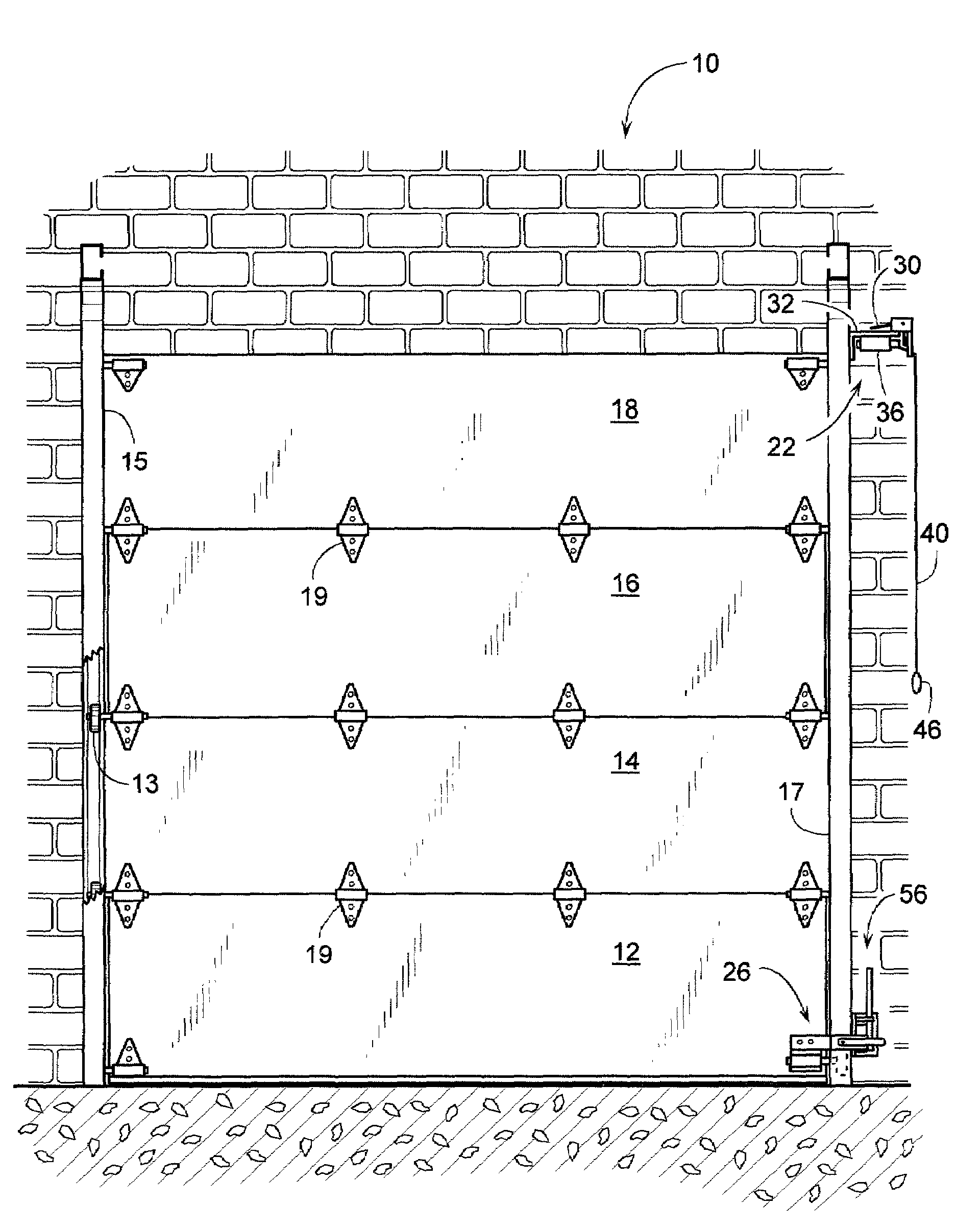
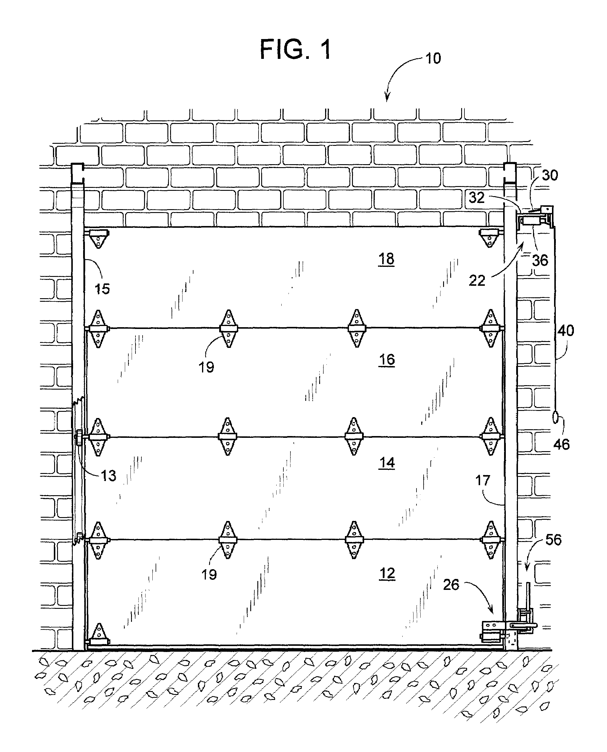
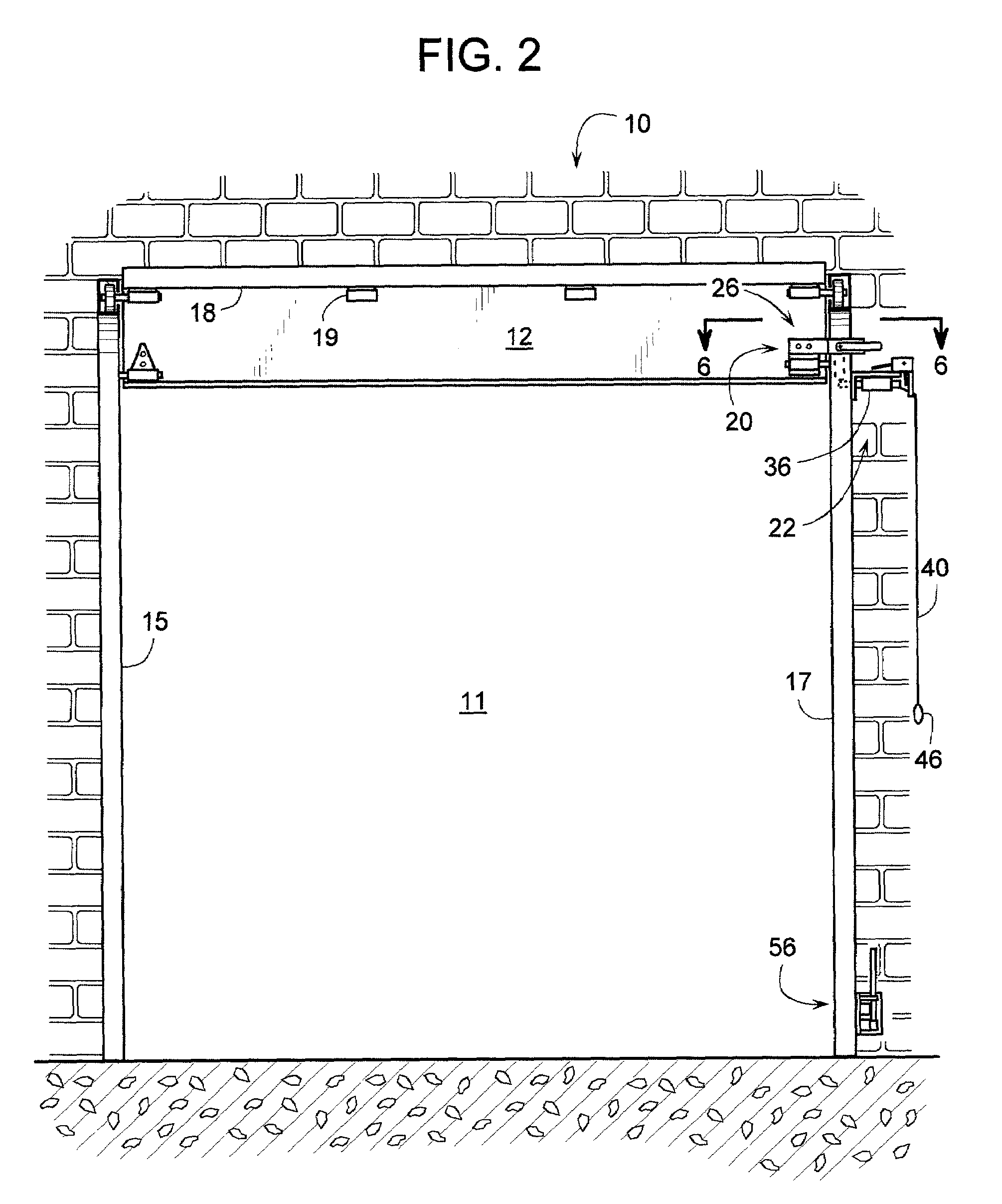
[0032]A sectional door 10, shown closed in FIG. 1 and open in FIG. 2, includes a series of door panels 12, 14, 16 and 18 that are interconnected along their adjacent horizontal edges by hinges 19. As door 10 opens or closes relative to a doorway 11, guide members, such as rollers 13, guide the movement of the panels along two lateral tracks 15 and 17. In this example, tracks 15 and 17 curve between horizontal and vertical; however, it is well within the scope of the invention to have tracks 15 and 17 run generally linearly or only curve slightly, so that when the door opens, the door panels move above doorway 11, but remain in a generally vertical or slightly angled orientation. To close door 10, the vertical sections of tracks 15 and 17 guide the panels to a vertical position across doorway 11. When door 10 opens, hinges 19 allow the panels to curve around onto the horizontal sections of tracks 15 and 17, where the door panels store horizontally overhead.

[0033]Typically, a torsion ...


PUM


Abstract

A door-latching system for a sectional door with multiple door panels helps hold the door at its fully open position in case the door's counterweight torsion spring fails to do so. The door-latching system includes a latch assembly that moves between a maintained release position and a door-blocking position. In the door-blocking position, the latch assembly helps hold the door open by providing an obstruction to the door panels. In the maintained release position, the latch assembly allows the door to move freely between open and closed positions without the door-latching system clacking as the door panels or their guide rollers travel past the latch assembly. Movement of the door panels automatically shifts the latch assembly from its release position to its door-blocking position, and manual actuation returns the latch assembly back to its release position. The latch assembly is especially suited for mounting to a track that guides the movement of the door panels.

Description

BACKGROUND OF THE INVENTION[0001]1. Field of the Invention[0002]The subject invention generally pertains to sectional doors and more specifically to a latch assembly for such a door.[0003]2. Description of Related Art[0004]A sectional door typically includes a series of panels whose adjacent horizontal edges are connected by hinges. As the door opens or closes, the door panels travel along two lateral tracks that, for some door styles, curve between horizontal and vertical. To close the door, the tracks guide the panels to a vertical position across the doorway. When the door opens, the hinges allow the panels to curve around onto horizontal sections of the tracks, where the door panels store horizontally overhead. For other door styles, the sectional door maintains a generally vertical, planar configuration and is stored more directly above the doorway. Such doors, regardless of their configuration, are often open and closed manually. To ease the operation of the door, a torsion sp...

Claims


Application Information

Patent Timeline
Patent Type & Authority Patents(United States)
IPC IPC(8): E05C1/02E05B17/22E05B47/02E05B65/00E05C17/00E05C17/60
CPCE05B47/0002E05B47/026E05B65/0021E05B17/22E05B47/0004E05C17/00E05C17/60Y10S292/36Y10T292/096Y10T292/1015Y10T292/1022Y10T292/1023Y10T292/1028
Inventor NODORFT, JEFF
Owner RITE HITE HLDG CORP
Learn More