

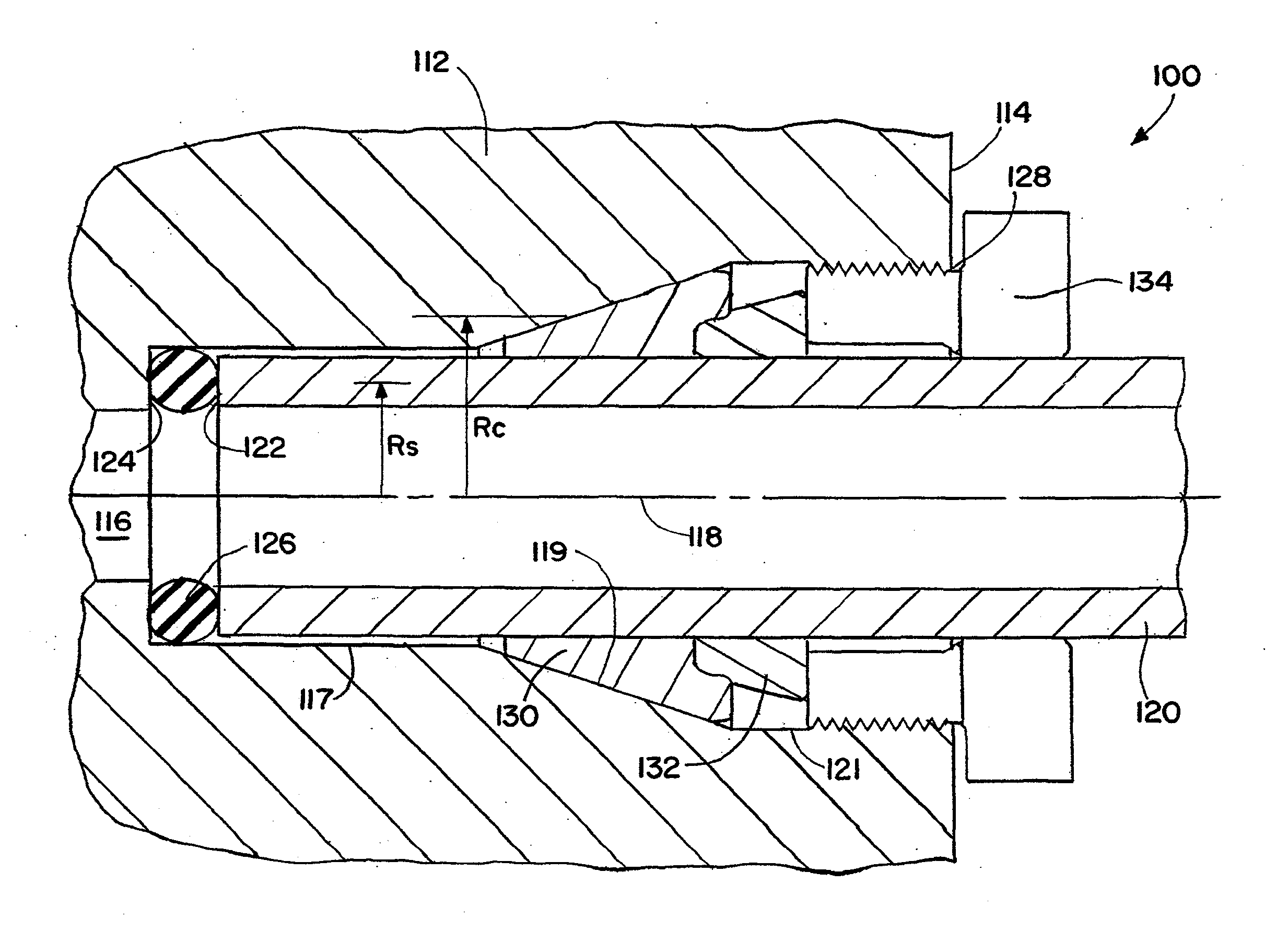
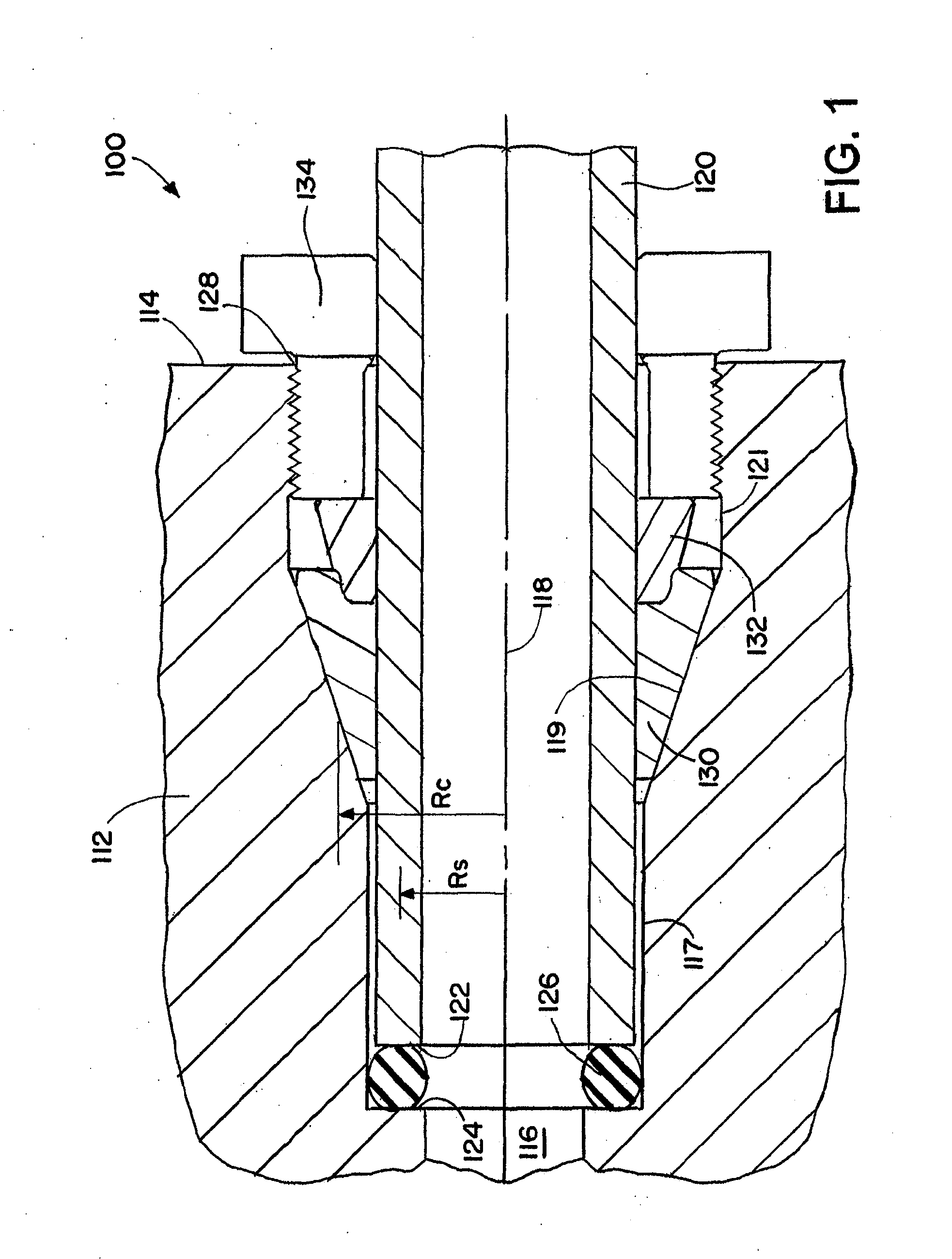
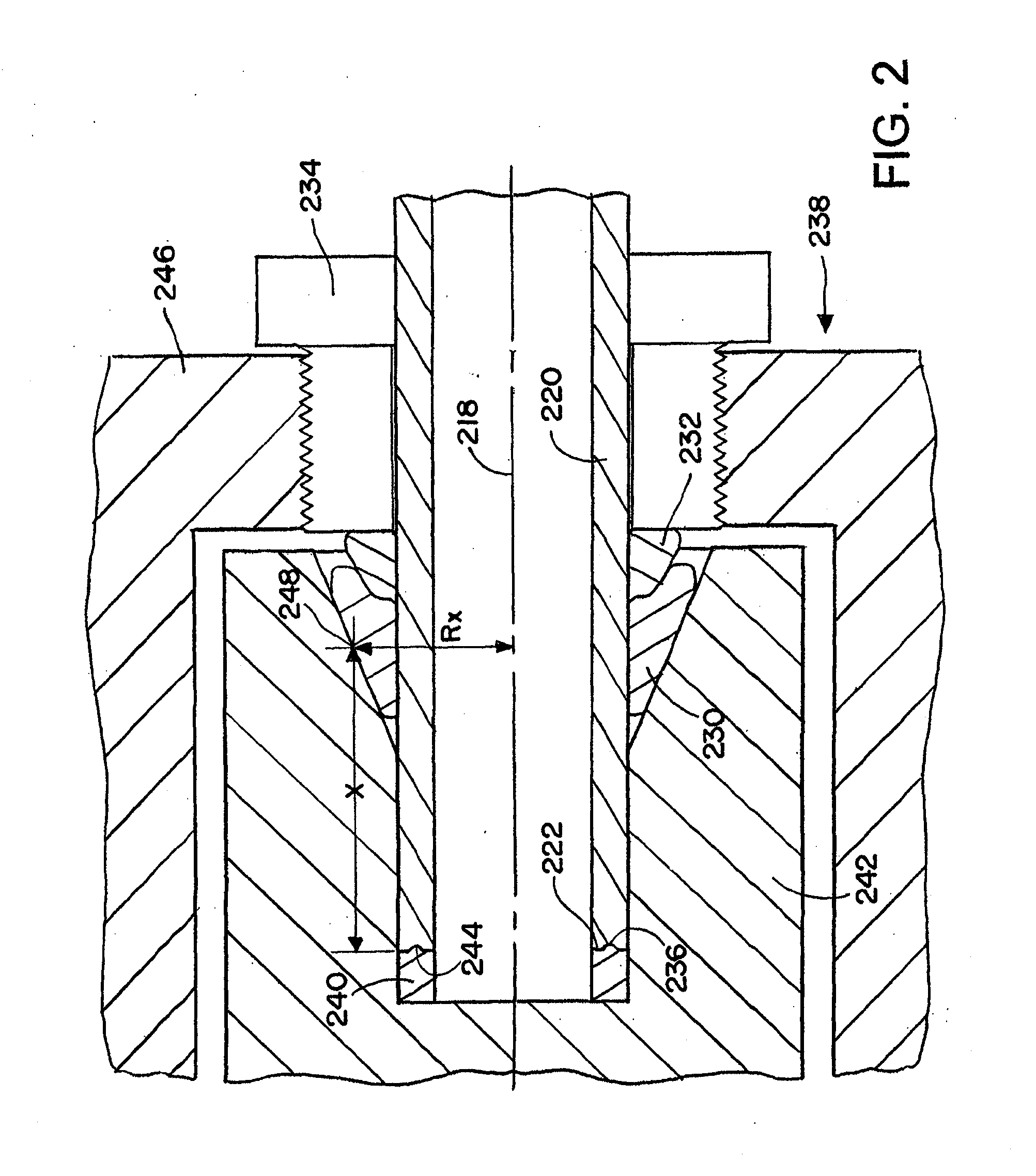
Tube and pipe end cartridge seal
a technology of end-capacity and sealing tube, which is applied in the direction of fluid pressure sealing joints, hose connections, pipe joints, etc., can solve the problems of reducing the choice of appropriate tube fittings, affecting sealing effect, and affecting sealing effect, so as to minimize the force against the seal, reduce the cost of preparation, and achieve the effect of effective sealing
- Summary
- Abstract
- Description
- Claims
- Application Information
AI Technical Summary
Benefits of technology
Problems solved by technology
Method used
Image

Examples
Embodiment Construction
[0071]For illustrative purposes, the precepts of a tube fitting assembly in accordance with the present invention are described in connection with a “straight” configuration such as for a union or coupling. It will be appreciated, however, that aspects of the present invention will find application in other fitting configurations, such as tees, elbows, and crosses, and as port connections for valves, cylinders, manifolds, sensors, and other fluid components. Further, the word “tube” and “tubing” is used throughout, but there may be cases where pipe or piping may also be appropriate for use and thus the reference to “tube” or “tubing” is intended to encompass pipe or piping unless otherwise indicated. Still further, the use of the term “tube fitting” or the like in this specification not only refers to the inverted tube fitting used for illustrative purposes, but also encompasses non-inverted (“standard”) tube fittings as well, though some of the advantages disclosed herein may not a...
PUM
| Property | Measurement | Unit |
|---|---|---|
| pressure | aaaaa | aaaaa |
| distance | aaaaa | aaaaa |
| force | aaaaa | aaaaa |
Abstract
Description
Claims
Application Information