Eureka AIR delivers breakthrough ideas for toughest innovation challenges, trusted by R&D personnel around the world.

Method for integration of source object into base image

Active Publication Date: 2006-01-03
COREL CORP +1
View PDF6 Cites 12 Cited by
  • Summary
  • Abstract
  • Description
  • Claims
  • Application Information

AI Technical Summary

Benefits of technology

[0010]The present invention provides a method for integration of a source object into a base image with an area overlapping the source object. The method comprises the steps of identifying similar border pixels, that is, pixels on two sides of a border between the source object and the base image having differences from each other smaller than a first threshold, calculating characteristic values of the similar border pixels in the source object and the base image using an energy function, creating a tonal map using the characteristic values, dividing the source object and the overlapped area in the base image into regions by segmentation filtering, identifying similar regions in the source object, each of which, in the characteristic values, has a difference smaller than a second threshold from the similar border pixels in the source object and has a difference smaller than a third threshold from one of the regions in the overlapped area having a difference smaller than a fourth threshold from the similar border pixels in the overlapped area, and applying the tonal map to the similar regions in the source object. The tonal value applied is subject to modification made by the energy distance between the source pixel and its corresponding pixel in the base image.
[0011]The present invention further

Problems solved by technology

Thus, the users expend much effort in blending them well.
However, this only reduces the sharpness of the edges locally without globally reducing or eliminating the color discontinuity between the object and the base image.
This requires considerable skill.
Further, undesired color changes may be made to portions of the object.
This can avoid unwanted changes, however, it is difficult and time-consuming to identify the individual regions using the selection tool if the object contains numerous many-edged or gradient-based images such as clouds.

Method used


Image

  • Method for integration of source object into base image
  • Method for integration of source object into base image
  • Method for integration of source object into base image

Examples


Embodiment Construction

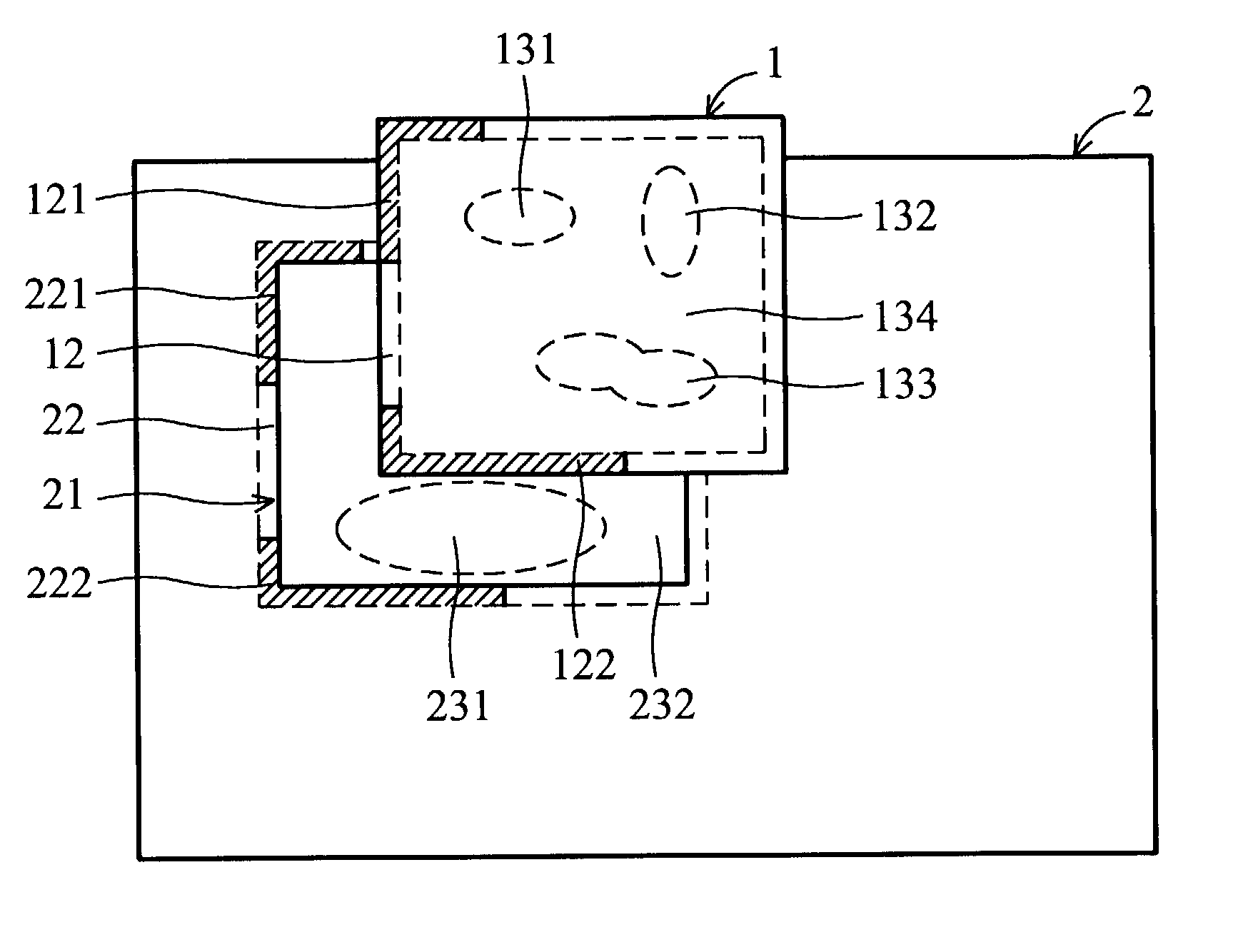
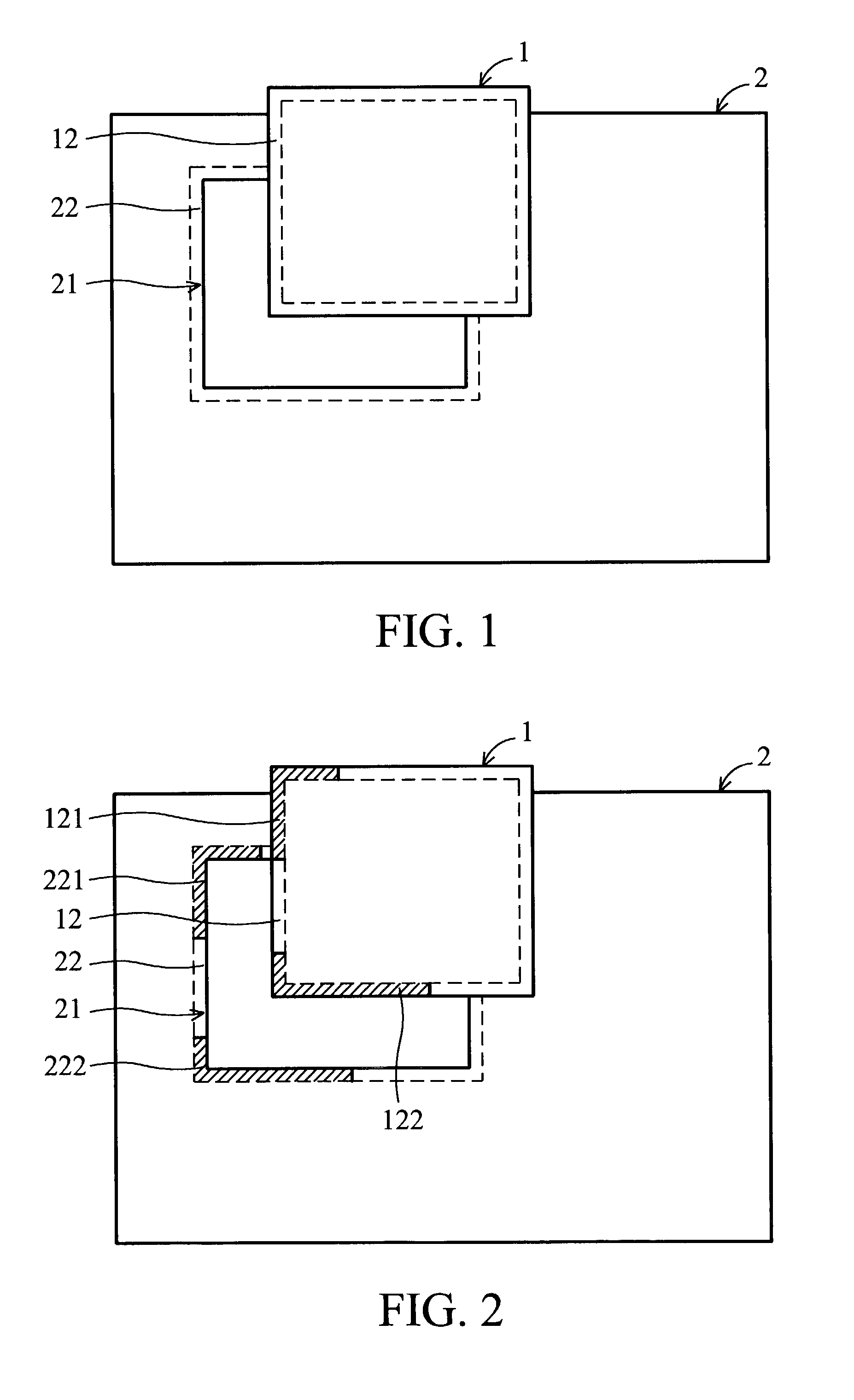
[0016]FIG. 5 is a flowchart of a method for integration of source object into base image according to one embodiment of the invention. The method will be explained by FIG. 5 accompanied with FIGS. 1˜4. The method integrates a source object 1 into a base image 2 as shown in FIG. 1. The source object 1 overlaps an area 21 in the base image 2.

[0017]In step 51, pixels in two border regions 12 and 22 respectively in the source object 1 and base image 2 are identified as border pixels. The border regions 12 and 22 are respectively on two sides of a border 3 between the source object 1 and base image 2. The widths of the border regions 12 and 22 are determined under consideration of processing speed. The processing speed will be higher if the widths are smaller.

[0018]In step 52, the border pixels having differences from each other smaller than a given threshold are identified as a group of similar border pixels. As shown in FIG. 2, there are two groups of the similar border pixels. One gro...


PUM


Abstract

A method for integration of a source object into a base image. The method comprises the steps of identifying similar border pixels, calculating characteristic values of the similar border pixels in the source object and the base image, creating a tonal map using the characteristic values, segmentation filtering the source object and the overlapped area into regions, identifying similar regions in the source object, each of which, in the characteristic values, has a difference smaller than a second threshold from the similar border pixels in the source object and smaller than a third threshold from one region in the overlapped area having an average difference smaller than a fourth threshold from the similar border pixels in the overlapped area, and applying the tonal map to the similar regions.

Description

BACKGROUND OF THE INVENTION[0001]1. Field of the Invention[0002]The present invention relates to a method for integration of a source object into a base image and particularly to a method for automatically detecting and adopting the color palette of the background region in the object / layer to the color palette of the background region in the base image.[0003]2. Description of the Prior Art[0004]As digital image capturing devices become cheaper and more popular, many PC users are interested in taking digital pictures and using a computer to make some changes to them for fun. In order to make it easy for general users to work on the images, many excellent tools are provided in image processing software applications. With these tools, it is possible to produce an artificially fabricated photo by integrating objects or image layers either cut out from a real photo or synthetically generated into another real photo or synthetically generated image used as a base image.[0005]A seamless i...

Claims


Application Information

Patent Timeline
IPC IPC(8): G06K9/36G06K9/00G06T5/50G06T7/40G06T11/00
CPCG06T5/50G06T11/00G06T7/408G06T7/90
Inventor CHEN, AUBREY KUANG-YU
Owner COREL CORP
Why Eureka
Eureka Blog
Learn More