Stable footwear that accommodates shear forces

a technology of shear force and stable footwear, applied in the field of footwear, can solve the problems of horizontal shear force acting on the wearer's body, reducing the horizontal shock absorption properties of the footwear, and injury to the wearer's ankles

Active Publication Date: 2006-01-10
REEBOK
View PDF64 Cites 24 Cited by
  • Summary
  • Abstract
  • Description
  • Claims
  • Application Information

AI Technical Summary

Benefits of technology

[0011]In a first embodiment of the present invention the transition layer comprises a more flexible material than that of the first and second layers. A plurality of deformable holes are contained within the more-flexible material. The transition layer is disposed between the first and second layers only on a lateral side of a heel section of the footwear. The deformable holes run horizontally through the transition layer from a lateral edge to a medial edge of the shoe. A more-resilient, lightweight support structure replaces the shear sole in a medial portion of the heel section. Additionally, a conventional sole which contains no transition layer, only a first layer, a second layer, and an outsole, is disposed in the forefront section of the footwear.
[0012]In another embodiment of the present invention, the shear sole configuration, including the ground engaging outsole, comprises the entire sole of the shoe. The transition layer again comprises a more flexible material than that of the first and second layers. Deformable holes disposed within the transition layer run horizontally therethrough from a lateral edge to a medial edge of the shoe or longitudinally therethrough from a proximal edge to a distal edge of the shoe.
[0013]Another embodiment of the present invention includes the shear sole, with the ground engaging outsole, comprising the entire heel portion of the shoe. The transition layer comprises a more flexible material than t

Problems solved by technology

However, horizontal shear forces are also acting on a wearer's body.
However, as the horizontal stability of the footwear increases, the horizontal shock absorption properties of the footwear decrease.
Such horizontal shear forces may cause injury to the wearer's ankles if the friction causes the shoe to stop before the wearer's foot can adjust to the change of motion.
Once again however, as the stability of such footwear has been increased to accommodate for the horizontal shear forces, the horizontal and vertical shock absorption properties of the footwear have decreased.

Method used


Image

  • Stable footwear that accommodates shear forces
  • Stable footwear that accommodates shear forces
  • Stable footwear that accommodates shear forces

Examples


Embodiment Construction

[0044]Preferred embodiments of the present invention are now described with reference to the figures, where like reference numbers indicate identical or functionally similar elements. Also in the figures, the left most digit of each reference number corresponds to the figure in which the reference number is first used. While specific configurations and arrangements are discussed, it should be understood that this is done for illustrative purposes only. A person skilled in the relevant art will recognize that other configurations and arrangements can be used without departing from the spirit and scope of the invention.

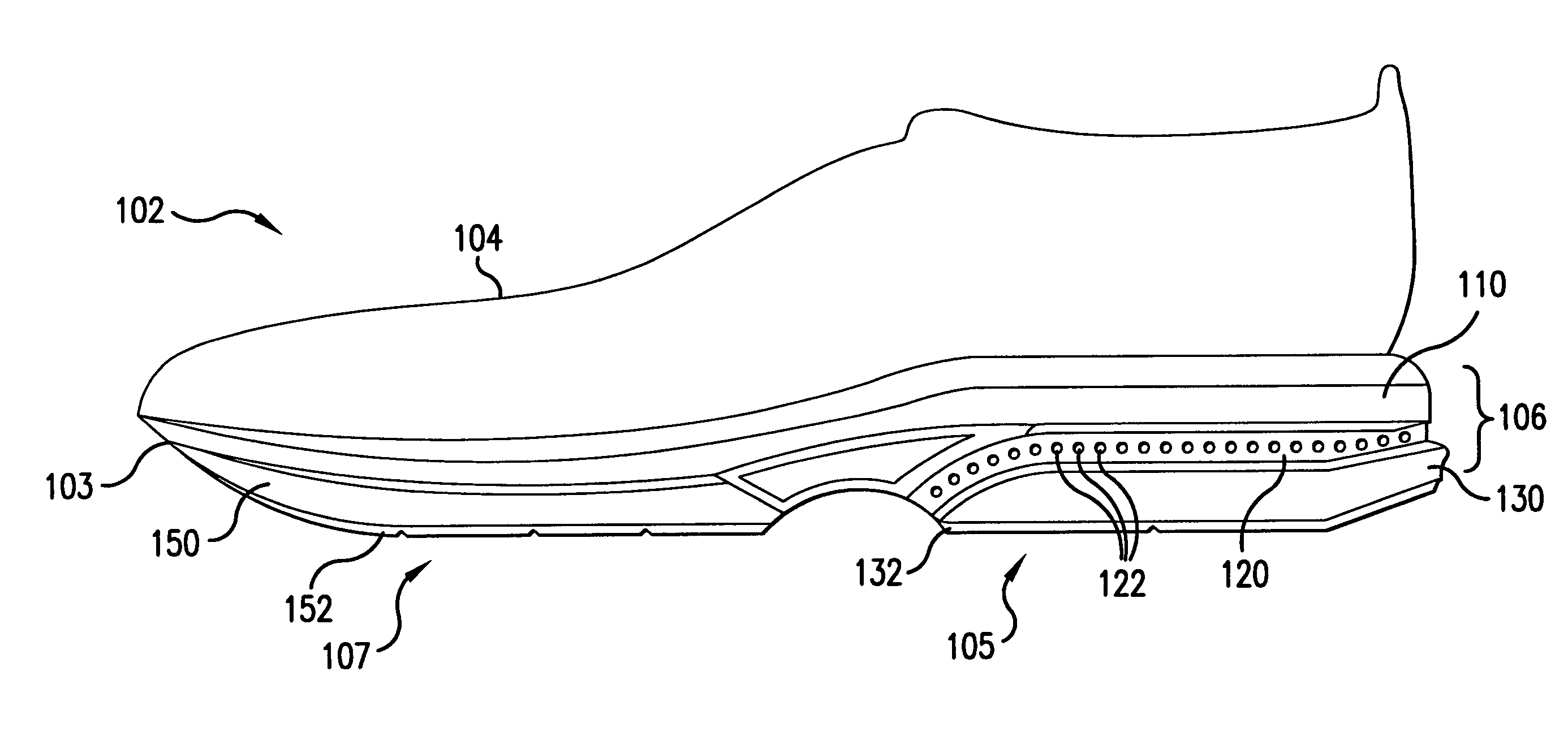
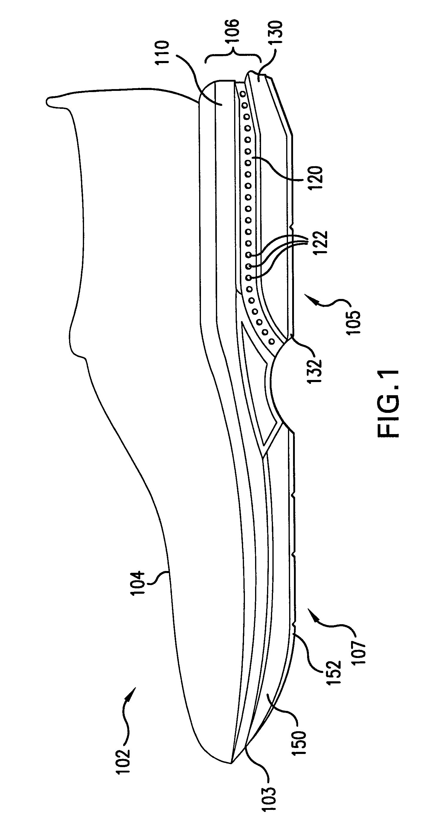
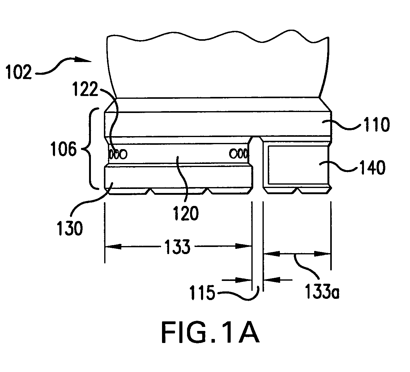
[0045]FIG. 1 depicts a lateral side view of a shoe 102 according to the present invention. Shoe 102 is preferably an athletic shoe, such as a running shoe, although the present invention is not limited to athletic shoes, but could also be any article of footwear, such as a sandal, a dress shoe, or the like. A left foot shoe is shown, but it will be apparent to one of or...


PUM

PropertyMeasurementUnit
Surfaceaaaaaaaaaa
Deformation enthalpyaaaaaaaaaa

Abstract

A shoe sole is described that provides both cushioning and stability. The sole has a plurality of layers, including a transition layer which allows relative motion between the layers adjacent to the transition layer. The relative motion between the layers of the sole reduces the impact of horizontal shear stresses on the wearer's feet and ankles. One such transition layer includes pliable material and deformable holes within the pliable material. Another transition layer includes at least two rigid plates held together by less rigid grommets or sidewalls. The transition layer may be disposed beneath the entire shoe or only portions of the shoe, with either a more conventional sole structure or rigid support members completing the sole.

Description

BACKGROUND OF THE INVENTION[0001]1. Field of the Invention[0002]The present invention relates to footwear, and in particular to an article of footwear designed to accommodate vertical forces and horizontal shear forces, both acting as the result of a foot strike, change in motion of the wearer, or both.[0003]2. Background of the Invention[0004]Soles in footwear, and especially athletic footwear, are designed to provide cushioning and stability. The cushioning aspect is normally designed to minimize the impact in the vertical direction caused when the wearer's body weight, moving in a downward vertical direction, acts on a wearer's foot as it strikes the ground. The stability feature is necessary to control the amount of horizontal motion of a wearer's foot in relation to a securely planted outsole of the footwear.[0005]Historically, due to a focus on the negative effects of vertical forces resulting from footstrikes during walking and running, many attempts have been made at providi...

Claims


Application Information

Patent Timeline
IPC IPC(8): A43B7/06A43B7/08A43B7/32A43B5/00A43B7/24A43B13/12A43B13/16A43B13/18
CPCA43B5/00A43B7/1425A43B7/144A43B13/186A43B13/12A43B13/16A43B13/181A43B7/24
Inventor LACORAZZA, DAVIDDAVIS, PAUL M.
Owner REEBOK
Why Eureka
Try Eureka