Support and cushioning system for an article of footwear

a technology of supporting and cushioning system and footwear, which is applied in the field of footwear, can solve the problems of pain, fatigue, injury, and the inability of the foot alone to effectively overcome many forces encountered during athletic activity, and achieve the effect of reducing discomfort for the wearer, reducing pain, and improving comfor

Inactive Publication Date: 2005-01-25
REEBOK
View PDF95 Cites 139 Cited by
  • Summary
  • Abstract
  • Description
  • Claims
  • Application Information

AI Technical Summary

Benefits of technology

In one embodiment, the central connecting passage contains an impedance means to restrict the flow of air between the heel chambers and the forefoot chambers. Thus, during heel strike, the air is prevented from rushing out of the heel chambers all at once. Thus, the air in the heel chambers provides support and cushioning to the wearer's foot during heel strike.
The flow of air into the forefoot portion causes the forefoot chambers to expand, which slightly raises the forefoot or metatarsal area of the foot. When the forefoot of the wearer is placed upon the ground, the expanded forefoot chambers help cushion the corresponding impact forces. As the weight of the wearer is applied to the forefoot, the downward pressure caused by the impact forces causes the forefoot chambers to compress, forcing the air therein to be thrust rearwardly through the central connecting passage into the heel portion

Problems solved by technology

One of the problems associated with shoes has always been striking a balance between support and cushioning.
Running, jumping, walking and even standing exert forces upon the feet and legs of an individual which can lead to soreness, fatigue, and injury.
Although the human foot possesses natural cushioning and rebounding characteristics, the foot alone is incapable of effectively overcoming many of the forces encountered during athletic activity.
This results in discomfort for the wearer which diminishes the incentive for further athletic activity.
Equally important, inadequately cushioned footwear can lead to injuries such as blisters, muscle, tendon and ligament damage, and bone stress fractures.
Improper footwear can also lead to other ailments, including back pain.
However, the sole should also possess enough resiliency to prevent the sole from being “mushy” or “collapsing,” thereby unduly draining the energy of the wearer.
However, foams such as EVA tend to break down over time, thereby losing their resiliency.
The overriding problem of these devices is that the cushioning means are inflated with a pressurized gas which is forced into the cushioning means, usually through a valve accessible from the exterior of the shoe.
There are several difficulties associated with using a pressurized fluid within a cushioning device.
Most notably, it may be inconvenient and tedious to constantly adjust the pressure or introduce a fluid to the cushioning device.
Moreover, it is difficult to provide a consistent pressure within the device thereby giving a consistent performance of the shoes.
In addition, a cushioning device which is capable of holding pressurized gas is comparatively expensive to manufacture.
Further, pressurized gas tends to escape from such a cushioning device, requiring the introduction of additional gas.
Finally, a valve which is visible to the exterior of the shoe negatively affects the aesthetics of the shoe; and increases the probability of the valve being damaged when the shoe is worn.
The problem with many of these cushioning devices is that they are either too hard or too soft A resilient member that is too hard may provide adequate support when exerting pressure on the member, such as when running.
However, the resilient member will likely feel uncomfortable to the wearer when no force is exerted on the member, such as when standing.
However, the member will likely not provide the necessary support when force is exerted on the member, such as when running.
Further, a resilient member that is too soft may actually drain energy from the wearer.

Method used


Image

  • Support and cushioning system for an article of footwear
  • Support and cushioning system for an article of footwear
  • Support and cushioning system for an article of footwear

Examples


second embodiment

FIG. 16 shows a bladder 1602 of the present invention. Bladder 1602 has a rear chamber 1604, a first front chamber 1606 and a second front chamber 1608. First and second front chambers 1606 and 1608 are connected via small passages 1610 formed by weld lines 1616. Bladder 1602 has connecting passages 1612 and 1614 formed by weld lines 1616, identical to bladder 1002. Connecting passages 1612 and 1614 connect rear chamber 1604 and first front chamber 1606.

third embodiment

FIG. 17 shows a bladder 1702 of the present invention. Bladder 1702 has a rear chamber 1704 and a plurality of front chambers 1706, 1708, 1710, 1712, 1714 and 1716. Front chamber 1706 and 1716 are connected via a small passage 1718. Similarly, front chambers 1708 and 1714 are connected via a small passage 1720 and front chambers 1710 and 1712 are connected via a small passage 1722. Bladder 1702 has connecting passages 1724, 1726 and 1728. Connecting passage 1724 connects rear chamber 1704 and front chamber 1706. Similarly, connecting passage 1726 connects rear chamber 1704 and front chamber 1708, and connecting passage 1728 connects rear chamber 1704 and front chamber 1710.

fourth embodiment

FIG. 18 shows a bladder 1802 of the present invention. Bladder 1802 has a rear chamber 1804 and a plurality of front chambers 1806, 1808 and 1810. Bladder 1802 has connecting passages 1812, 1814 and 1816. Connecting passage 1812 connects rear chamber 1804 and front chamber 1806. Similarly, connecting passage 1814 connects rear chamber 1804 and front chamber 1808, and connecting passage 1816 connects rear chamber 1804 and front chamber 1810.

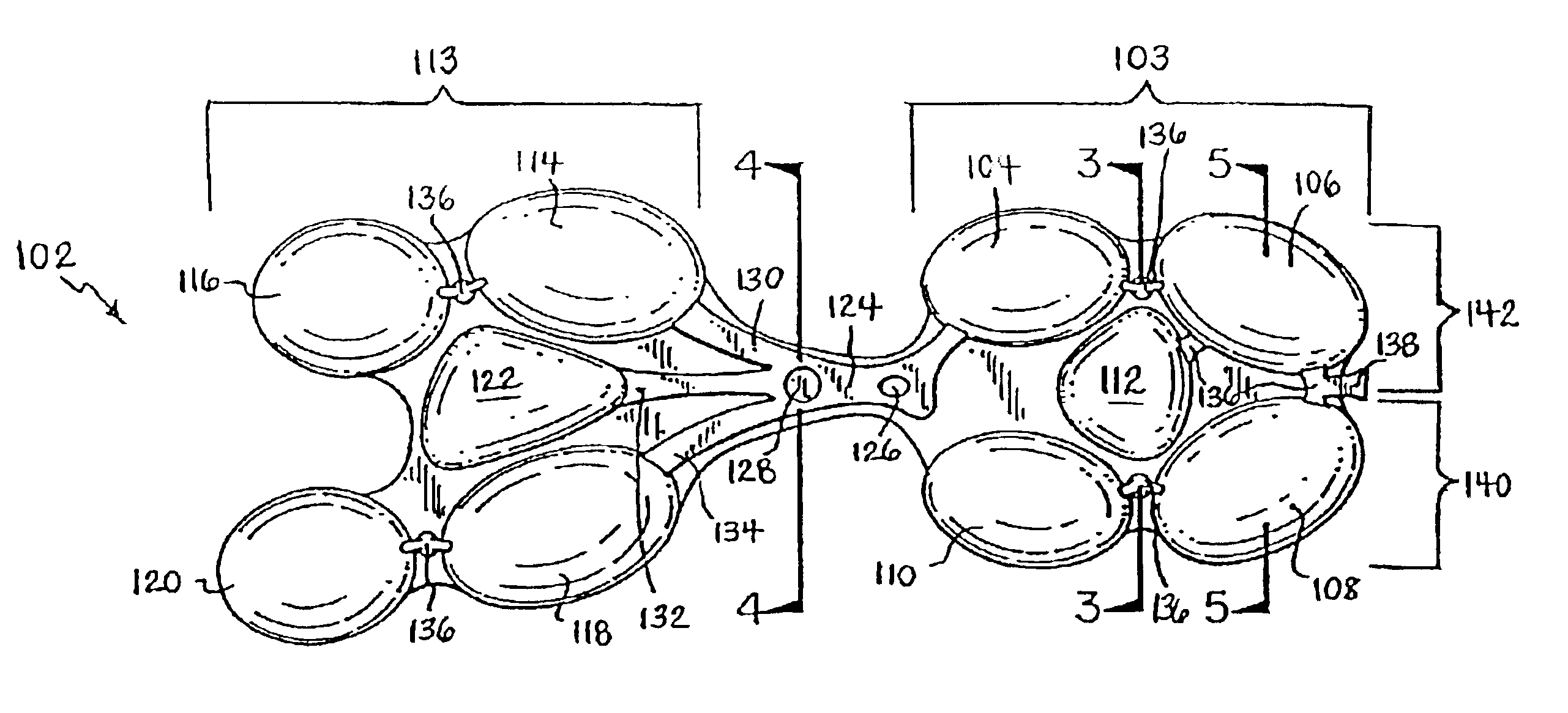
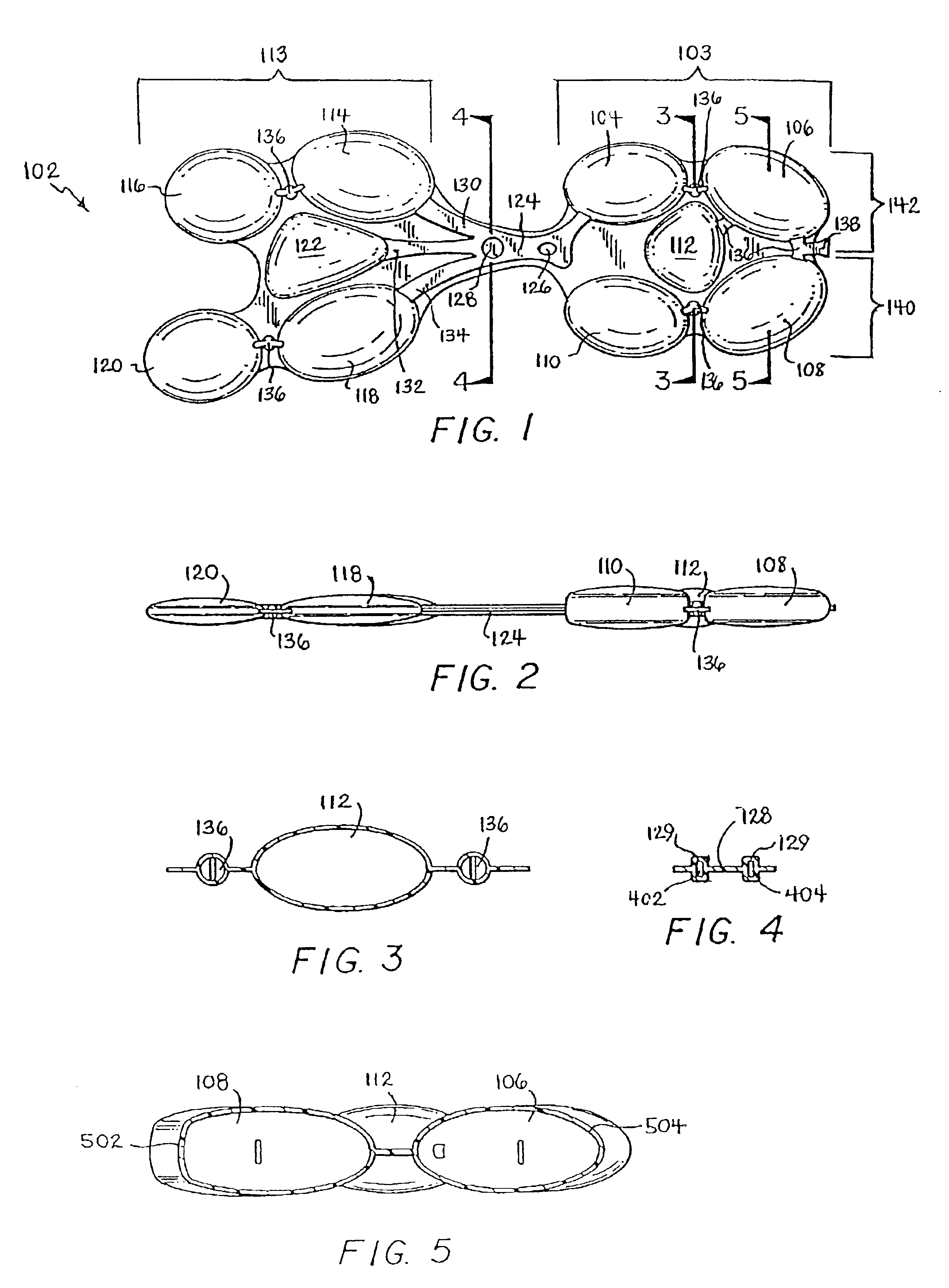
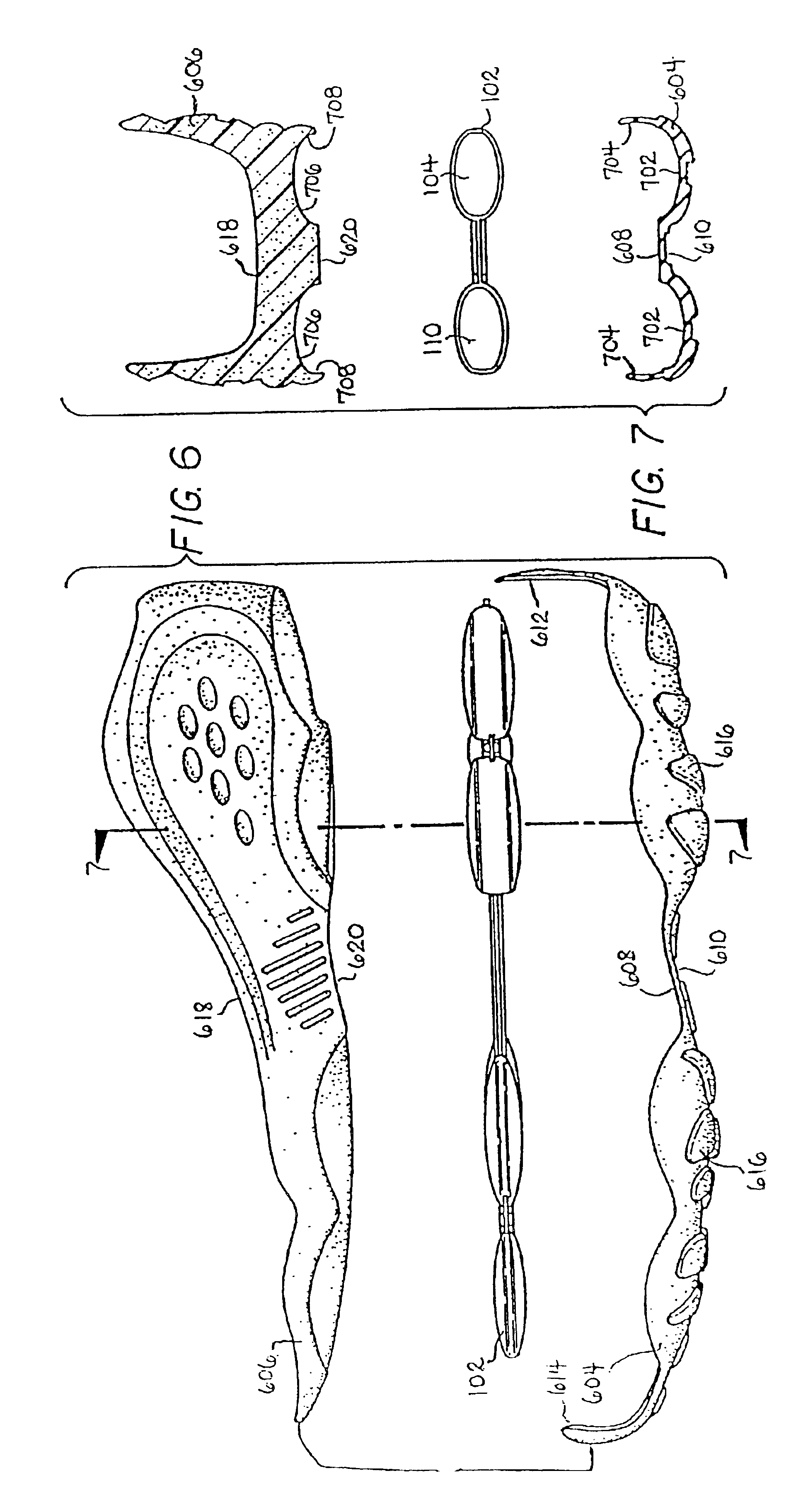
With reference to FIGS. 1 and 5, it will be appreciated that resilient insert 102 comprises an insert which may be positioned within different areas of an article of footwear. Accordingly, although resilient insert 102 is shown as being positioned between outsole 604 and midsole 606 in FIG. 6, it is to be understood that resilient insert 102 may also be positioned within a cavity formed within a midsole or between a midsole and an insole Mien positioned between a midsole and an outsole, resilient insert 102 may be visible from the exterior of the ...


PUM


Abstract

A cushioning member for an article of footwear. The cushioning member is a flexible bladder having a fluidly interconnected heel chamber and forefoot chamber. The bladder is disposed above the sole and beneath the wearer's foot to provided added cushioning to the wearer. The bladder contains air at slightly above ambient pressure and can be formed by thermoforming or by welding two sheets of resilient, flexible material together. A connecting passage fluidly connects the heel chamber and the forefoot chamber. The connecting passage is narrow to control the flow of air between the two chambers.

Description

BACKGROUND OF THE INVENTION1. Field of the InventionThis invention relates generally to footwear, and more particularly to an article of footwear having a system for providing cushioning and support for the comfort of the wearer.2. Related ArtOne of the problems associated with shoes has always been striking a balance between support and cushioning. Throughout the course of an average day, the feet and legs of an individual are subjected to substantial impact forces. Running, jumping, walking and even standing exert forces upon the feet and legs of an individual which can lead to soreness, fatigue, and injury.The human foot is a complex and remarkable piece of machinery, capable of withstanding and dissipating many impact forces. The natural padding of fat at the heel and forefoot, as well as the flexibility of the arch, help to cushion the foot. An athlete's stride is partly the result of energy which is stored in the flexible tissues of the foot. For example, during a typical walk...

Claims


Application Information

Patent Timeline
Patent Type & Authority Patents(United States)
IPC IPC(8): A43B13/20A43B13/18
CPCA43B13/203
Inventor LITCHFIELD, PAUL E.MONTROSS, MATTHEW J.SMITH, STEVEN F.WHITE, J. SPENCERJESSIMAN, ALEXANDER W.
Owner REEBOK
Why Eureka
Try Eureka