Fluid level measuring device

Inactive Publication Date: 2006-01-24
ORSCHELN PRODS
View PDF107 Cites 9 Cited by
  • Summary
  • Abstract
  • Description
  • Claims
  • Application Information

AI Technical Summary

Benefits of technology

[0008]The instant invention solves problems associated with conventional fluid level measuring systems by providing a handle associated with a dipstick that is free to swivel or rotate freely within a plastic handle.

Problems solved by technology

This causes inter-engagement of t

Method used


Image

  • Fluid level measuring device
  • Fluid level measuring device
  • Fluid level measuring device

Examples


Embodiment Construction

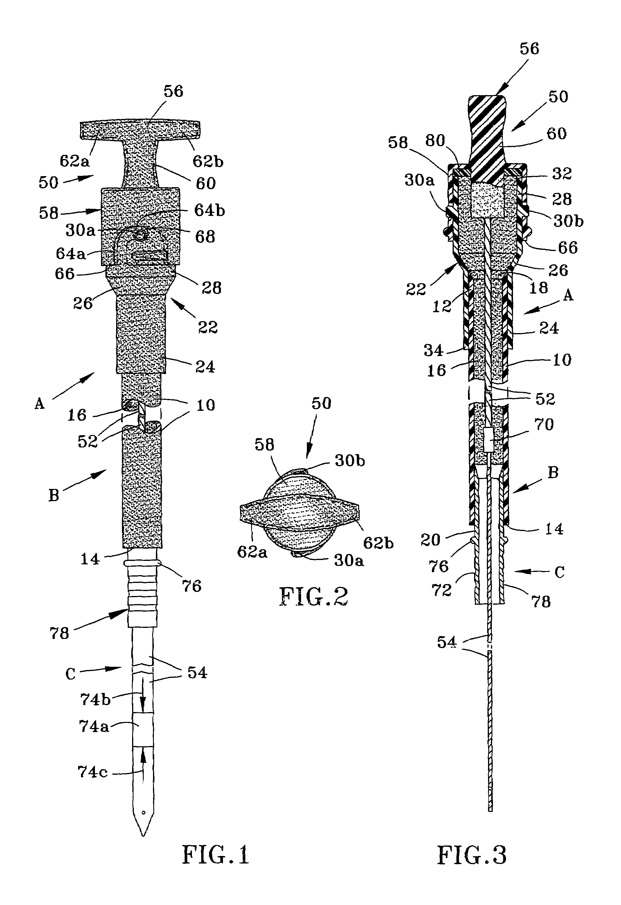
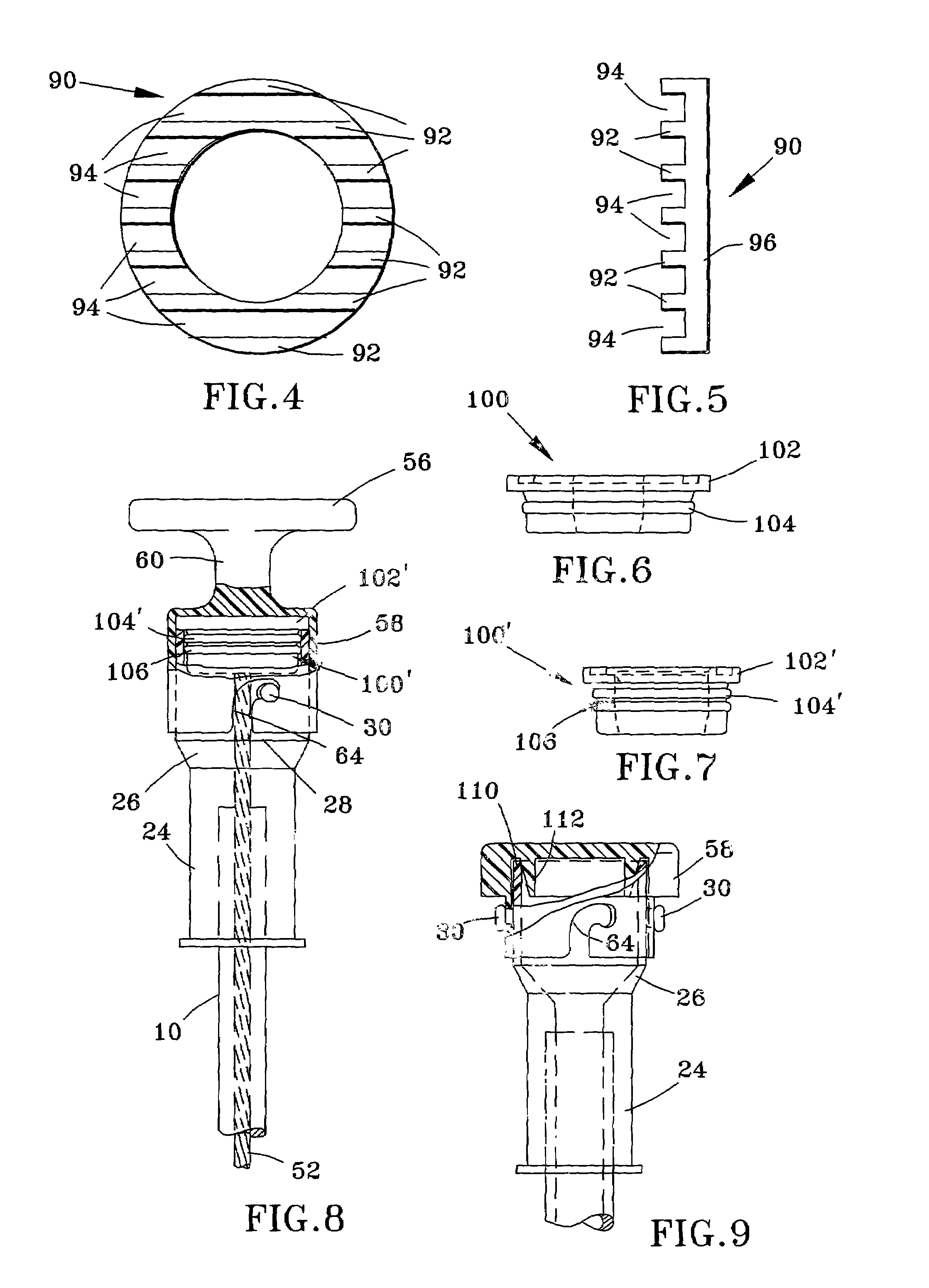
[0035]One aspect of the instant invention relates to a fluid level indicator system comprising a handle, a rotatably mounted shaft and dipstick mounted within the handle, and a stationary tube having an opening for receiving the handle. The rotatably mounted shaft can be over-molded by the plastic handle in a manner that permits the shaft to rotate (or prevents the plastic from permanently bonding to the shaft). The handle can be received within or around the stationary tube opening.

[0036]At least a portion of the shaft is contacted with a fluid that prohibits the over-molding plastic handle from permanently bonding to the shaft. While any suitable material can be employed, examples of suitable materials comprise commercially available injection mold release agents, oils, lubricants, among others capable of preventing a permanent bond between the shaft and over-molded plastic. One material comprises a polymeric carrier such as an acrylic, urethane or epoxy and heat expandable sphere...


PUM


Abstract

A fluid level measuring device, also referred to as a dipstick, for measuring the fluid level in a fluid reservoir or tank, such as an oil pan or transmission reservoir in an internal combustion engine. The fluid level measuring device includes a stationary tube assembly in which a rotatable dipstick assembly is disposed. The dipstick assembly includes a fluid level indicator measuring blade attached to an elongated shaft that is molded into a plastic handle assembly. The plastic handle assembly includes a bayonet type locking mechanism for locking the handle to the stationary tube assembly. A compressible seal forms a pressurized seal between the stationary tube assembly and the handle.

Description

CROSS-REFERENCE TO RELATED PATENTS AND PATENT APPLICATIONS[0001]The subject matter of the invention is related to U.S. Pat. No. 6,314,808, filed on Nov. 24, 1997, and U.S. Pat. No. 6,453,740, filed on Sep. 05, 2001; both entitled “Fluid Level Measuring Device”. The disclosure of these patents is hereby incorporated by reference.[0002]The subject matter herein claims benefit under 35 U.S.C. Section 119(e) of U.S. Patent Application Ser. No. 60 / 326,636, filed Oct. 01, 2001, and entitled “Fluid Level Measuring Device”; the disclosure of which is hereby incorporated by reference.FIELD OF THE INVENTION[0003]The subject invention is directed to a device used to measure fluid levels, and more particularly, to dipsticks used to measure fluid levels by contacting an indicator at one end of the dipstick into a fluid holding compartment.BACKGROUND OF THE INVENTION[0004]With internal combustion engines, transmissions, and other machinery requiring fluids for lubrication and cooling, it is known...

Claims


Application Information

Patent Timeline
IPC IPC(8): G01F23/00G01F23/04
CPCG01F23/04
Inventor DOUGHERTY, JOHN MICHAELSLABAUGH, KAREN S.MAREK, STEVEN
Owner ORSCHELN PRODS
Why Eureka
Try Eureka