

Golf ball
a golf ball and golf ball technology, applied in the field of golf balls, can solve the problems of impaired aerodynamic symmetry and insufficient symmetry of polygonal dimples of golf balls, and achieve the effect of excellent aerodynamic symmetry
Inactive Publication Date: 2006-01-31
DUNLOP SPORTS CO LTD
View PDF11 Cites 56 Cited by
- Summary
- Abstract
- Description
- Claims
- Application Information
AI Technical Summary
Benefits of technology
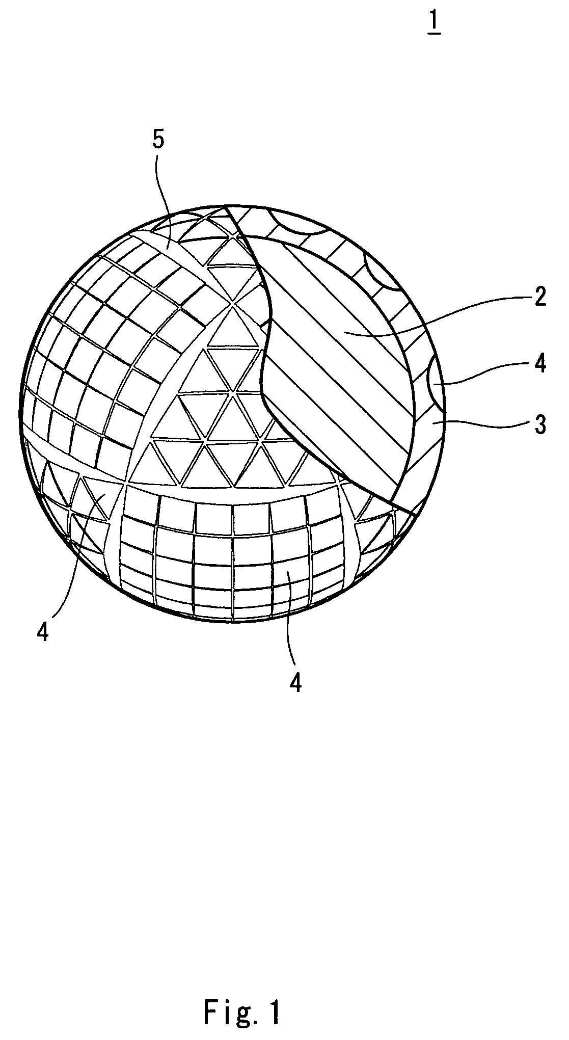
[0009]A golf ball according to the present invention has numerous dimples, which include polygonal dimples provided on the surface thereof. In this golf ball, when a phantom spherical face thereof is comparted into multiple spherical regular polygons with comparting lines formed by casting a reflection of sides of a semiregular polyhedron inscribed in the phantom spherical face onto the phantom spherical face, the spherical regular polygons include the dimples arranged therein. Proportion of the polygonal dimples occupied in total number of the dimples is equal to or greater than 50%. According to this golf ball, the polygonal dimples are responsible for the flight performance. According to this golf ball, the dimple pattern in which a semiregular polyhedron is employed is responsible for the aerodynamic symmetry. On behalf of the synergistic effects of the polygonal dimples and the semiregular polyhedron, excellent aerodynamic symmetry is imparted to the golf ball.
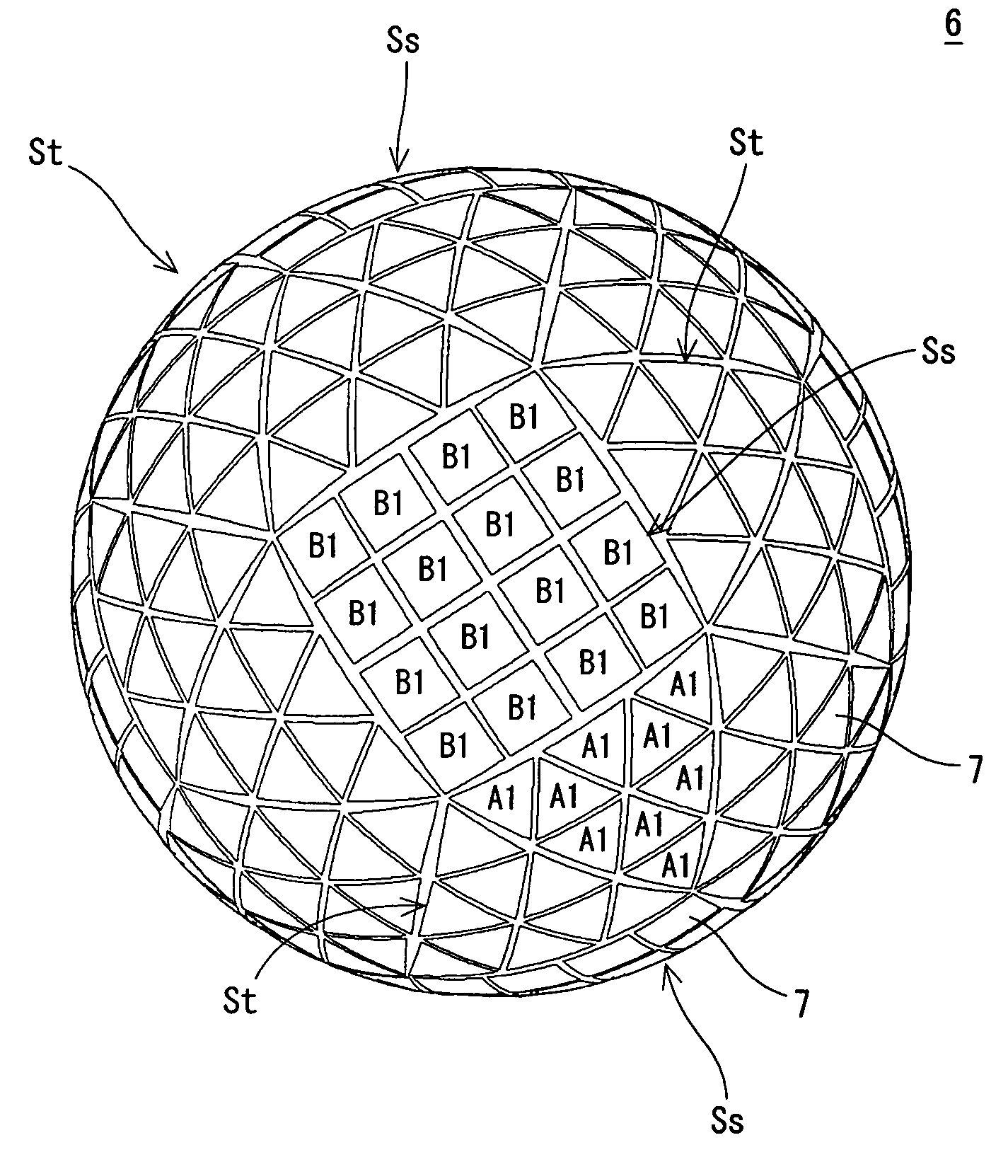
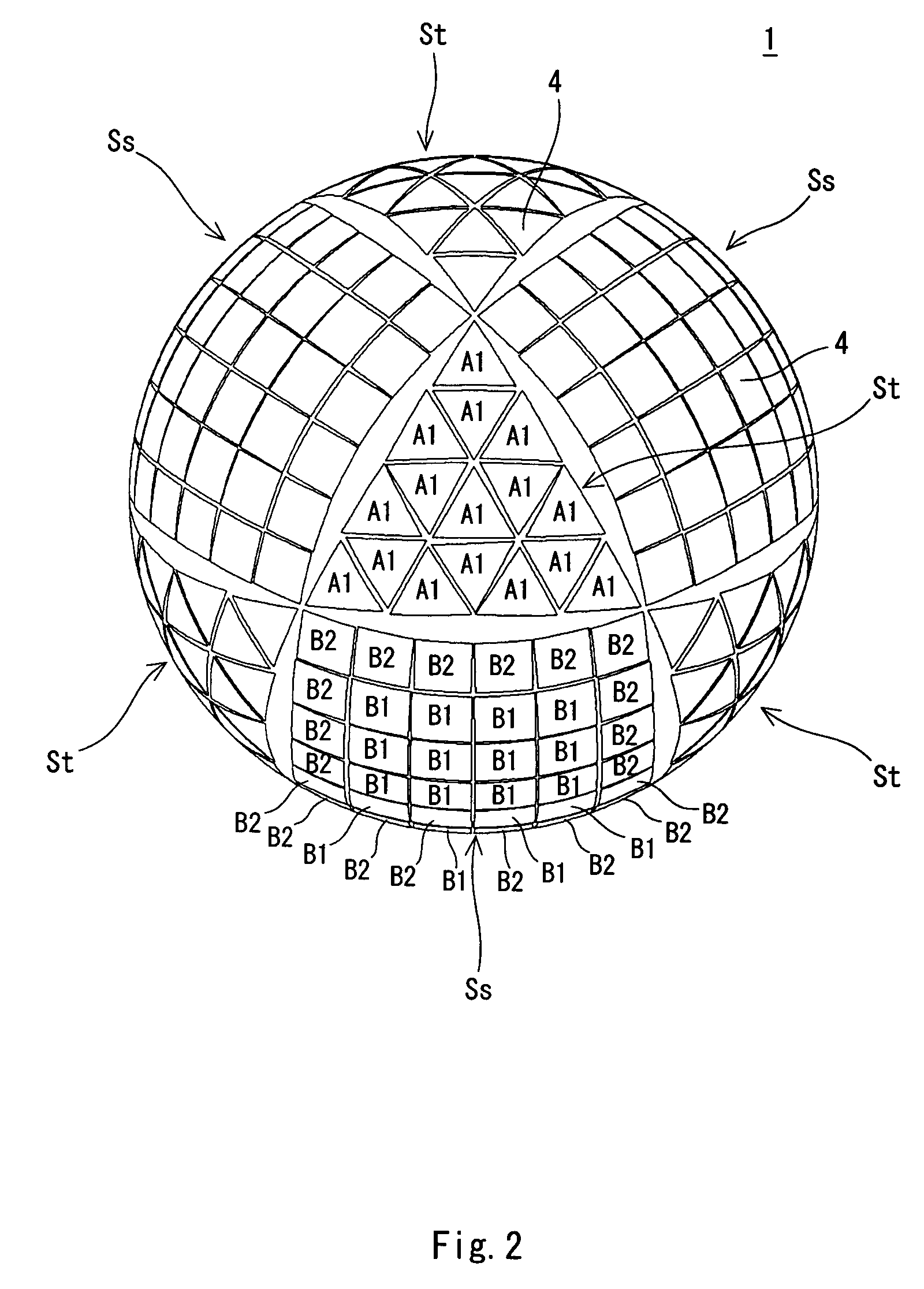
[0012]Typically, the number of vertices of the first spherical regular polygon is 3, and the number of vertices of the second spherical regular polygon is 4. In other words, the first spherical regular polygon is the spherical regular triangle, and the second spherical regular polygon is the spherical square. By arranging regular triangular dimples mainly on the spherical regular triangles, and arranging square dimples mainly on the spherical squares, an excellent dimple effect is achieved.
Problems solved by technology
Polygonal dimples have insufficient symmetry compared to circular dimples.
When such polygonal dimples are arranged in an orderly array, there is the possibility that aerodynamic symmetry as a golf ball is impaired.
Method used
View moreImage
Smart ImageViewing Examples

Examples
example 1
[0046]A core consisting of a solid rubber was placed into a mold, and an ionomer resin composition was injected around the core to form a cover layer. Accordingly, the golf ball of Example 1 having a dimple pattern illustrated in FIG. 2 and FIG. 3 was obtained. External diameter of the ball was 42.70±0.03 mm, and the compression was 85±2.
Login to View More PUM
 Abstract
Surface of a golf ball 1 is comparted into 8 spherical regular triangles St and 6 spherical squares Ss by comparting lines that are formed by casting a reflection of sides of the cuboctahedron inscribed in the phantom spherical face onto the phantom spherical face. On the spherical regular triangle St are arranged regular triangular dimples A1. On the spherical square Ss are formed square dimples B1 and B2. Dimple patterns of respective spherical regular triangles St are identical with each other. Dimple patterns of respective spherical squares Ss are identical with each other. It is also permitted that the snub cube is envisioned, and the surface is comparted into spherical regular triangles St and spherical squares Ss. Surface area occupation percentage of dimples 4 is preferably equal to or greater than 70%.
Description
[0001]This Nonprovisional application claims priority under 35 U.S.C. § 119(a) on Patent Application No(s). 2003-027174 filed in JAPAN on Feb. 4, 2003, the entire contents of which are hereby incorporated by reference.BACKGROUND OF THE INVENTION[0002]1. Field of the Invention[0003]The present invention relates to golf balls. More particularly, the present invention relates to dimple patterns of golf balls.[0004]2. Description of the Related Art[0005]Golf balls have numerous dimples provided on the surface thereof. A role of the dimples involves causing turbulent flow detachment through disrupting the air flow around the golf ball during the flight (hereinafter, referred to as “dimple effect”). By causing the turbulent flow detachment, a detachment point of air from the golf ball shifts backwards leading to the reduction of a drag coefficient (Cd). The turbulent flow detachment promotes the difference of positions of the upper detachment point and the lower detachment point resulting...
Claims
Login to View More Application Information
Patent Timeline
 Patent Type & Authority Patents(United States)
IPC IPC(8): A63B37/12A63B37/00
CPCA63B37/0004A63B37/0021A63B37/0009A63B37/0006
Inventor SAJIMA, TAKAHIRO
Owner DUNLOP SPORTS CO LTD