Process for designing rugged pattern on golf ball surface

a golf ball surface and rugged technology, applied in the field of golf balls, can solve the problems of inferior aerodynamic symmetry, short flight distance of golf balls with inferior aerodynamic symmetry, and large difference between these two trajectories, and achieve excellent aerodynamic symmetry and contribute to the flight performance of golf balls

Inactive Publication Date: 2015-06-16
TOYOHASHI UNIVERSITY OF TECHNOLOGY +1
View PDF5 Cites 0 Cited by
  • Summary
  • Abstract
  • Description
  • Claims
  • Application Information

AI Technical Summary

Benefits of technology

[0022]On the surface of a golf ball according to the present invention, a large number of craters are formed by recesses. These craters prompt turbulent flow separation. These craters contribute to the flight performance of the golf ball. Because these craters are arranged in a random manner, the pattern does not have directional properties. The golf ball has excellent aerodynamic symmetry.

Problems solved by technology

A golf ball having a large difference between these two trajectories, that is, inferior aerodynamic symmetry, does not conform to the rules.
A golf ball with inferior aerodynamic symmetry has a short flight distance because the aerodynamic characteristic of the golf ball for PH rotation or for POP rotation is inferior.
Such a golf ball has inferior aerodynamic symmetry.
However, the uniqueness is not sufficiently eliminated.
This golf ball has insufficient aerodynamic symmetry.
The flight distance of the golf ball is insufficient.
However, the causes have not been clarified yet, and a general theory for the improvements has not been established.

Method used


Image

  • Process for designing rugged pattern on golf ball surface
  • Process for designing rugged pattern on golf ball surface
  • Process for designing rugged pattern on golf ball surface

Examples


example 1

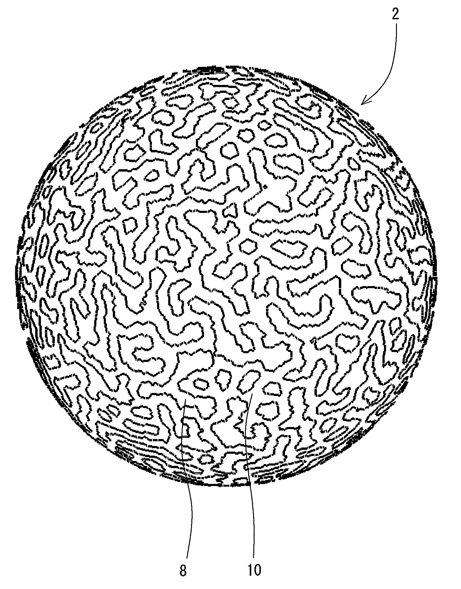
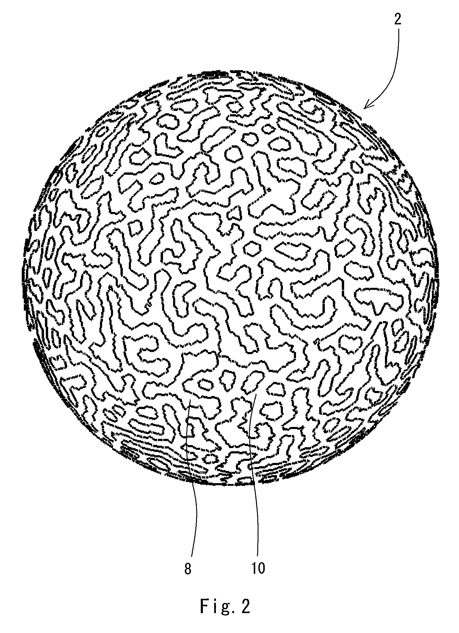
[0146]By the method shown in FIG. 3, the rugged pattern shown in FIG. 2 was designed. The details of the factors that influence the pattern are as follows.

[0147]Number of cells: 47415

[0148]First concentration W1: 1.00

[0149]Second concentration W2: −0.60

[0150]Index radius R1: 2.5

[0151]Index radius R2: 4.0

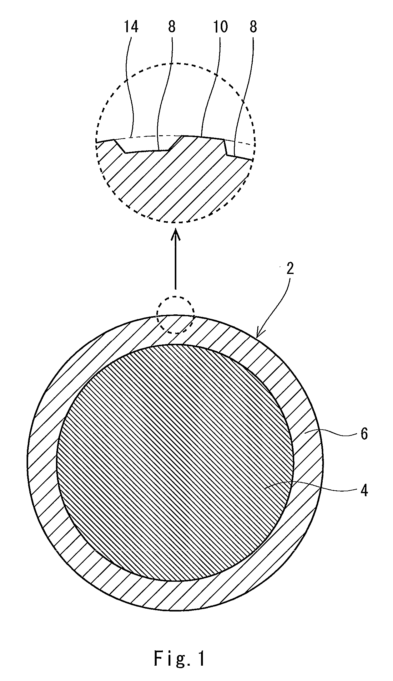
[0152]Depth of crater (Ra-Rb): 0.213 mm

examples 2 to 4

[0153]Rugged patterns of Examples 2 to 4 were designed in a similar manner as Example 1, except the values of the factors were as shown in the following Table 2. The rugged pattern of Example 2 is shown in FIG. 16. The rugged pattern of Example 3 is shown in FIG. 17. The rugged pattern of Example 4 is shown in FIG. 18.

[0154]

TABLE 2ExamplesExample 1Example 2Example 3Example 4Number of cells47415769948826688266First concentration W11.001.001.001.00Second concentration W2−0.60−0.60−0.60−0.60Index radius R12.502.502.502.20Index radius R24.004.004.004.00Depth Ra-Rb (mm)0.2130.2150.2150.151Number of craters2704107001300(rough estimate)


PUM


Abstract

A golf ball 2 has numerous craters 8 on its surface. The craters 8 are arranged randomly. Of the surface of the golf ball 2, a part other than the craters 8 is a land 10. By the craters 8 and the land 10, a rugged pattern is formed on the golf ball 2. A process for designing the rugged pattern includes the steps of:(1) assuming a plurality of states;(2) assuming a large number of cells on a spherical surface;(3) deciding an initial state of each cell;(4) determining whether or not to change a state of the each cell based on states of a plurality of cells located adjacent to the each cell;(5) updating the state of the each cell based on the determination; and(6) assigning a land 10 or a recess to the each cell according to the state of the each cell.

Description

[0001]This application claims priority on Patent Application No. 2008-146056 filed in JAPAN on Jun. 3, 2008. The entire contents of this Japanese Patent Application are hereby incorporated by reference.BACKGROUND OF THE INVENTION[0002]1. Field of the Invention[0003]The present invention relates to golf balls. Specifically, the present invention relates to processes for designing a rugged pattern on a golf ball surface.[0004]2. Description of the Related Art[0005]Golf balls have a large number of dimples on the surface thereof. The dimples disturb the air flow around the golf ball during flight to cause turbulent flow separation. By causing the turbulent flow separation, separation points of the air from the golf ball shift backwards leading to a reduction of drag. The turbulent flow separation promotes the displacement between the separation point on the upper side and the separation point on the lower side of the golf ball, which results from the backspin, thereby enhancing the lif...

Claims


Application Information

Patent Timeline
Patent Type & Authority Patents(United States)
IPC IPC(8): A63B37/12A63B37/00G06F17/50
CPCG06F17/50A63B37/007A63B37/0011A63B37/0007G06F30/00
Inventor KIM, HYOUNGCHOLONUKI, MASAHIDEYAMADA, KANAMEKAWAMURA, SHOZO
Owner TOYOHASHI UNIVERSITY OF TECHNOLOGY
Why Eureka
Try Eureka