Tilt outboard wing for tilt rotor aircraft

a tilt-rotor aircraft and outboard wing technology, applied in vertical landing/take-off aircraft, aircraft navigation control, transportation and packaging, etc., can solve the problems of high wing aspect ratio, weight and structural dynamics considerations, high level of buffeting, etc., to reduce the buffeting of aircraft and improve the flight performance of aircraft with outboard wings

Active Publication Date: 2010-09-28
KAREM ABE
View PDF19 Cites 33 Cited by
  • Summary
  • Abstract
  • Description
  • Claims
  • Application Information

AI Technical Summary

Benefits of technology

[0013]The present invention provides wing extensions outboard of the tilting rotor nacelles in tilt-rotor aircraft. The purpose of such extensions is to increase in wing span and wing aspect ratio, and thereby to increase the lift / drag ratio and the resulting aircraft efficiency and fuel economy. Extensive analysis with rotor analysis code (Wayne Johnson's CAMRAD II) indicates that in cruise mode the positive effects of the outboard wing and the rotor sense of rotation are additive, with little or no reduction in the positive contribution of either.
[0014]The wing extensions (for convenience—outboard wings) tilt with the rotor nacelle. This avoids the down load that would have acted on the outboard wing in hover, and therefore avoids the need to increase rotor size, engine power and gearbox torque to create the required additional lift.
[0017]From a method perspective, flight performance of an aircraft with outboard wings can be improved by upwardly deflecting the trailing edge flap while transitioning between forward cruise flight and take-off and landing mode. As used herein, the term “take-off and landing mode” includes VTOL, STOL, and STOVL.
[0018]In another aspect, methods of reducing buffeting of an aircraft having a tilting wing comprise including a trailing edge wing flap on the wing, and upwardly deflecting the flap while transitioning between forward cruise flight and take-off and landing mode. In that respect it should be appreciated that the term “aircraft having tilting wing” is used interchangeably herein with a “tilt wing aircraft”.
[0021]In such rotorcraft embodiments upward deflecting of the trailing edge flap can advantageously be used to: improve flight performance while transitioning between forward cruise flight and take-off and landing mode; reducing buffeting; and to increase the lift to drag ratio.

Problems solved by technology

High wing aspect ratios are limited by structures, weight and structural dynamics considerations.
Among the disadvantages of tilt-wing aircraft is the high level of buffeting caused by the massive stall of the wing in forward flight with the wing and rotors at steep angle close to hover position.
A remaining problem in tilt-rotor aircraft is that the low aspect ratio results in low lift / drag ratio, and consequently low aircraft efficiency and fuel economy.

Method used


Image

  • Tilt outboard wing for tilt rotor aircraft
  • Tilt outboard wing for tilt rotor aircraft
  • Tilt outboard wing for tilt rotor aircraft

Examples


Embodiment Construction

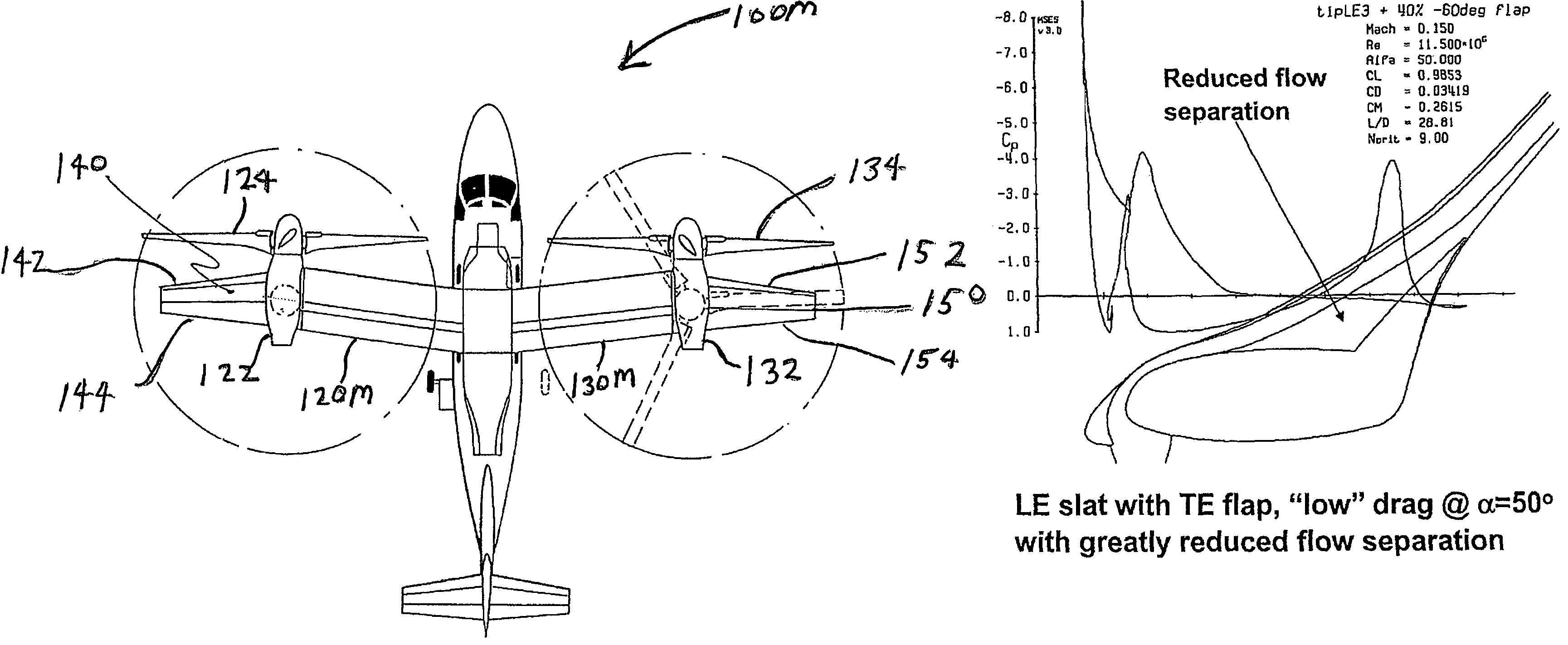
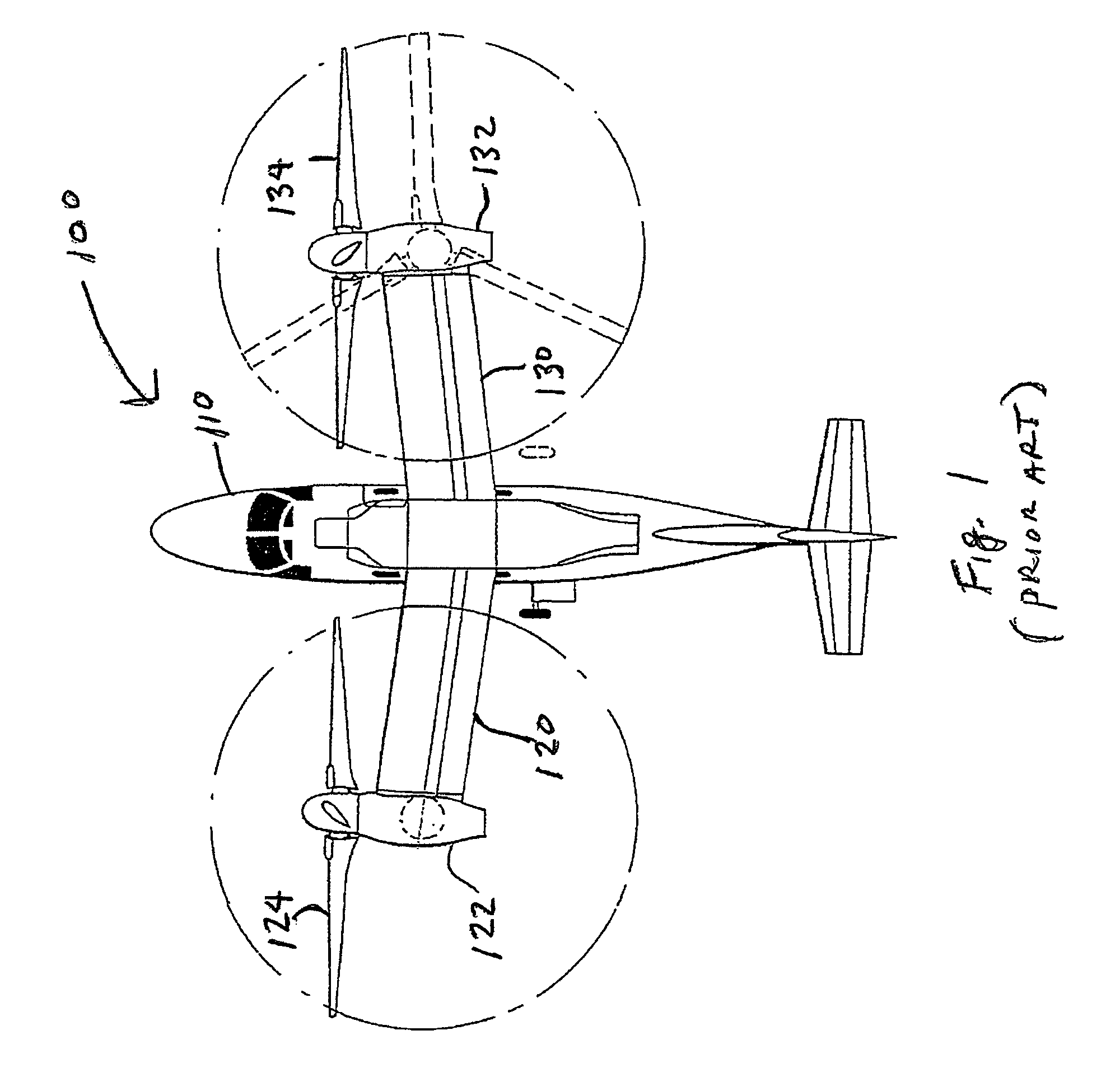
[0026]In FIG. 1 a rotorcraft 100 generally includes a fuselage 110, a left wing 120 with tilting nacelle 122 and rotor 124, and a right wing 130 with tilting nacelle 132 and rotor 134. As with other prior art aircraft of this type, each of the wings 120, 130 has a wing aspect ratio is 5.5. To illustrate the tilt-rotor aspect of the design in a simplified manner, the nacelles 122, 132, and the right rotor 134 are shown in the lifting configuration in dashed lines.

[0027]It should be appreciated that although rotorcraft 100 is depicted here in a substantially to-scale model of a Bell / Agusta BA 609, the drawing should be interpreted as being representative of tilt-rotorcraft in general. In particular, it is contemplated that the inventive subject matter could also be applied to twin tilt-rotor, quad tilt-rotor configuration, etc.

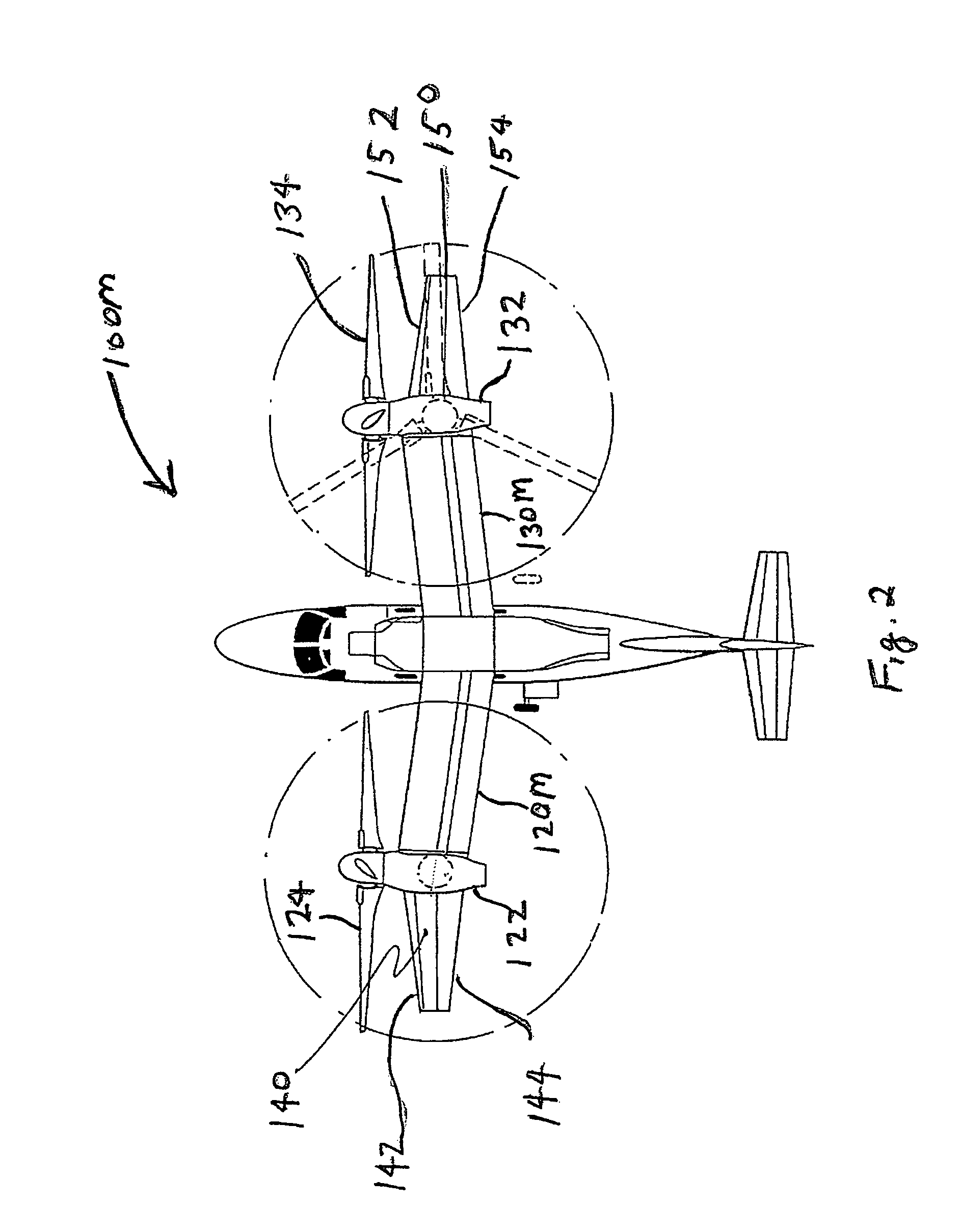
[0028]In FIG. 2 the rotorcraft 100M of FIG. 1 has been modified to include outboard wings 140, 150, which increase the wing aspect ratio (ratio of wing span to ...


PUM


Abstract

Tilt-rotor aircraft experience increased efficiency and fuel economy by including wing extensions outboard of the tilting nacelles. Stall and buffeting during conversion from rotor-born hover to wing-born forward flight are reduced to an acceptable level using wide chord flaps deflected upwards by at least 15-20°, preferably in combination with leading edge slats. The outboard wing or wing portion preferably has a span at least 25-40% of a span of the inboard section, and a total surface area at least 10-20% the total surface area of the corresponding inboard section.

Description

[0001]This application claims priority to U.S. Provisional Application Ser. No. 60 / 708,646 filed Aug. 15, 2005.FIELD OF THE INVENTION[0002]The field of the invention is tilt-rotor aircraft.BACKGROUND OF THE INVENTION[0003]The successful development of the tilt-rotor aircraft in the last 30 years (Bell XV-15, Bell / Boeing V-22 and Bell / Agusta 609) make the tilt-rotor configuration a commercially viable starting point for efficient Vertical Take-Off and Landing (VTOL) aircraft.[0004]Tilt-rotor aircraft are aircraft which use the lift of rotors to hover and VTOL. These aircraft tilt their rotors so that in forward flight the lift is provided by the wing and the forward thrust by the rotors. The term “proprotor” can also be used to describe rotors that function as a propulsive device in forward flight and as lifting device in helicopter mode.[0005]The cruise efficiency of aircraft as measured by its payload carried times the distance traveled per consumed fuel (for example Lb of Payload×...

Claims


Application Information

Patent Timeline
Patent Type & Authority Patents(United States)
IPC IPC(8): B64C27/28B64C15/12B64C3/50
CPCB64C29/0033
Inventor KAREM, ABE
Owner KAREM ABE
Why Eureka
Try Eureka