Electronic signal transmission and switching jack

a switching jack and signal transmission technology, applied in the direction of contacts, tumbler/rocker switches, coupling device connections, etc., can solve the problems of not allowing users to configure the circuits connected to individual devices, users of these types of devices and jack fields have a very complex and dense wiring environment within their physical plants

Inactive Publication Date: 2006-01-31
COMMSCOPE TECH LLC
View PDF36 Cites 21 Cited by
  • Summary
  • Abstract
  • Description
  • Claims
  • Application Information

AI Technical Summary

Problems solved by technology

This type of design does not allow the users to configure the circuits connected to individual devices and required all devices connected to a particular jack field to be configured identically.
In addition, users of these types of devices and jack fields have very complex and dense wiring environments within their physical plants.

Method used


Image

  • Electronic signal transmission and switching jack
  • Electronic signal transmission and switching jack
  • Electronic signal transmission and switching jack

Examples


Embodiment Construction

[0055]Reference will now be made in detail to exemplary aspects of the present invention that are illustrated in the accompanying drawings. Wherever possible, the same reference numbers will be used throughout the drawings to refer to the same or like parts.

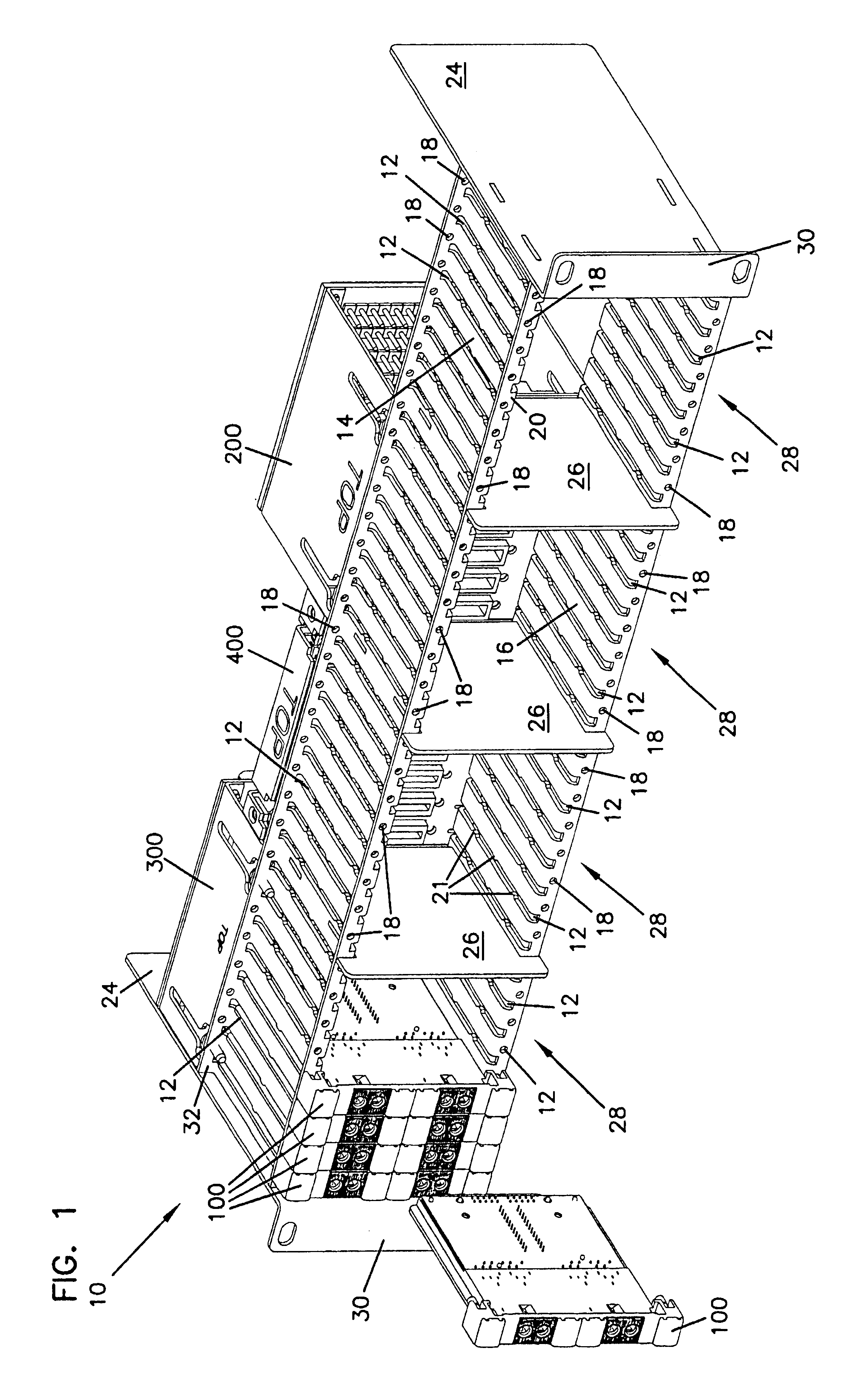
[0056]Referring now to FIG. 1, an audio signal transmission chassis 10 is shown with four switching modules 100 mounted within the chassis and a fifth switching module 100 in position to be inserted into chassis 10. Switching modules 100 are mounted by engaging card slots 12 in upper plate 14 and lower plate 16. Removable fasteners are then inserted through each module 100 and engaged by openings 18 in first upper plate flange 20 and first lower plate flange 22. The fasteners are not shown in FIG. 1 but may include any type of suitable removable fastener such as a screw. Chassis 10 comprises upper plate 14 and lower plate 16 which are joined to each other by end plates 24 and a series of intermediate plates 26. Mounting flanges 3...


PUM


Abstract

The present invention relates to an electronic signal switching module with connectors on a first side for connecting with a variety of devices and sources and with jacks for receiving patch cords on a second side. The switching modules include two position switches in the circuitry connecting the jacks with the connectors which allow the module to be configured as a straight-through patching module, a fully normal module with paired jacks or a half normal module with paired jacks. One alternative of the invention utilizes card edge connectors on the first side. Another aspect of the invention involves a chassis for holding a plurality of switching modules adjacent to and electronically connected with a plurality of connecting modules. The switching modules may also include designation lenses adjacent to the jacks for holding indicia.

Description

FIELD OF THE INVENTION[0001]The present invention relates to electronic signal transmission and switching. More specifically, the present invention relates to multi-function, multi-circuit switching jack modules for the audio, broadcast and entertainment industries.BACKGROUND OF THE INVENTION[0002]Analog and digital audio signals are transmitted over balanced and shielded twisted pair cables. These cables include a pair of insulated conductors, either stranded or solid wire, which are surrounded by a metal foil shield. The shield serves to reduce the impact of external electromagnetic inference on the signal being transmitted over the cable and also to reduce the electromagnetic field generated by the signals being transmitted over the cable.[0003]In a professional audio and video industry application, a large number of such cables will be in use to carry signals from sources to processing devices such as mixers or equalizers and further to amplifiers or other downstream devices. Th...

Claims


Application Information

Patent Timeline
Patent Type & Authority Patents(United States)
IPC IPC(8): H01R13/70H01R13/703H04Q1/02H04Q1/14
CPCH01H23/006H01R13/703H01R12/721H04Q2201/12H04Q2201/10
Inventor FOLLINGSTAD, MICHAELADAMS, PETERPETERS, JEFFREY
Owner COMMSCOPE TECH LLC
Why Eureka
Try Eureka