Reflection-control system and method

a transmission line and reflection technology, applied in the direction of logic circuits, digital transmission, increasing modifications, etc., can solve the problems of electromagnetic noise, affecting signal integrity, and deteriorating signal integrity and transmission line behavior

Active Publication Date: 2006-01-31
TAMIRAS PER PTE LTD LLC
View PDF3 Cites 118 Cited by
  • Summary
  • Abstract
  • Description
  • Claims
  • Application Information

AI Technical Summary

Problems solved by technology

As the speed of digital circuits increases, a number of characteristics related to signal integrity and transmission line behavior deteriorate.
Further, as signal speeds increase, electromagnetic noise increases, thus affecting signal integrity.
At today's speeds, even the passive elements of a high-speed design, features such as the wires and printed circuit board (PCB) traces, for example, as well as chip packages, can contribute significantly to overall signal delay and exacerbate timing and logic errors.
The secular move toward ever-increasing speeds without commensurate improvements in transmission line signal management and termination will make signal integrity preservation an escalating issue in high speed electronics.
Lower transmission line impedances and lower driver output impedances typically result, however, in higher power consumption as lower impedances dissipate more power.
Unfortunately, termination structures occupy space and dissipate power.
Series terminations typically present, however, a relatively high series impedance that can impede signal integrity by increasing the transmission line RC characteristic.
This scheme uses little PCB space but, like many parallel termination schemes, can dissipate power even after the transmission line has been driven HIGH.
It also can be difficult to terminate a complex topology like a DRAM address net.
When in series mode, this termination does not switch to a lower impedance when the line is driven HIGH and, consequently, does not mitigate the RC effect of the higher impedance that is often characteristic of series termination strategies.
This system and many others like it, allow multiple devices to drive signals on the same transmission line, but they still exhibit problems inherent to parallel termination schemes such as higher power consumption and imprecise impedance matching, for example.
This reflection wave or impulse can travel with an uncontrolled characteristic on the transmission line and impede or, in some cases, prevent accurate signal reception.

Method used


Image

  • Reflection-control system and method
  • Reflection-control system and method
  • Reflection-control system and method

Examples


Embodiment Construction

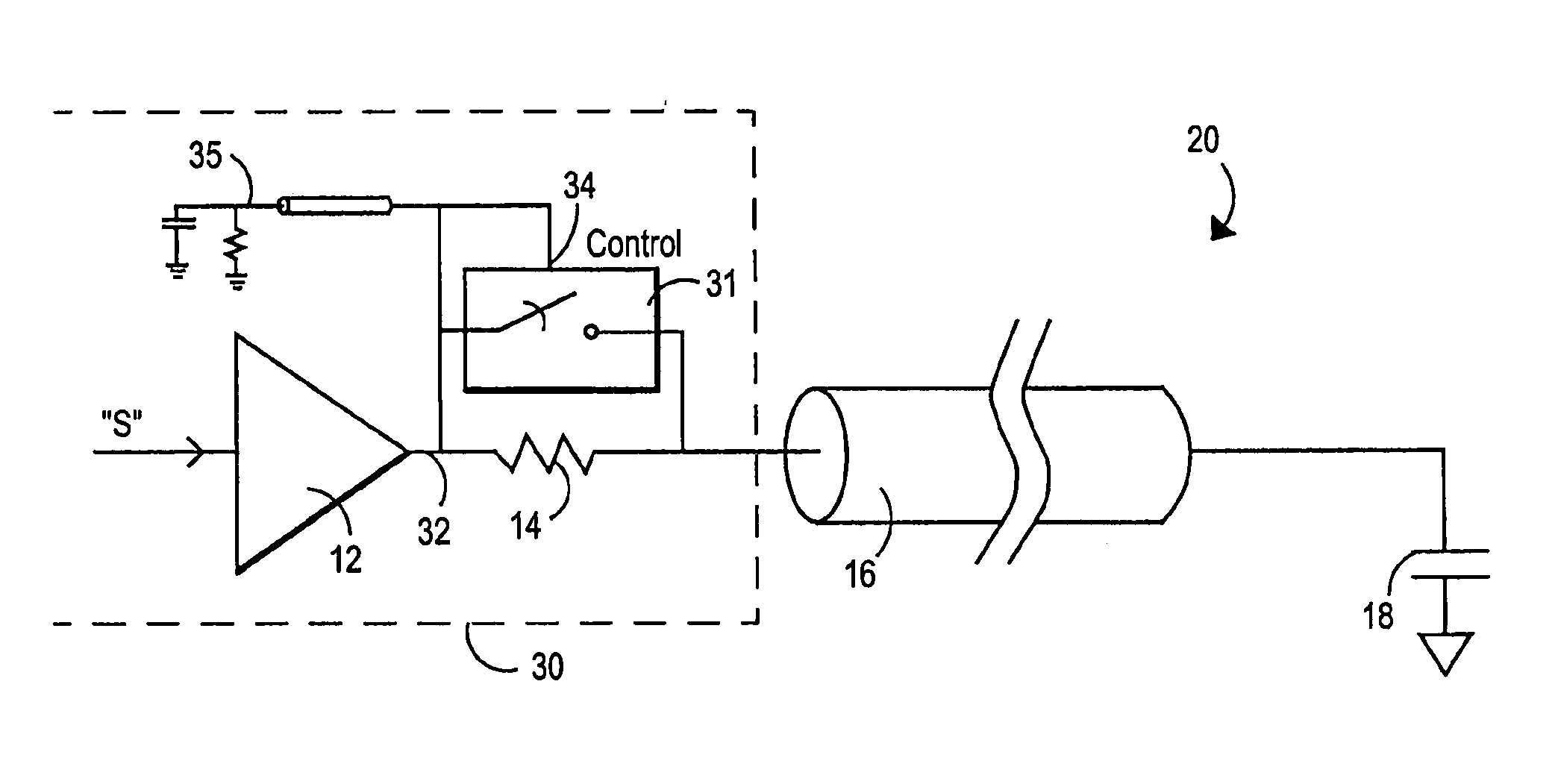
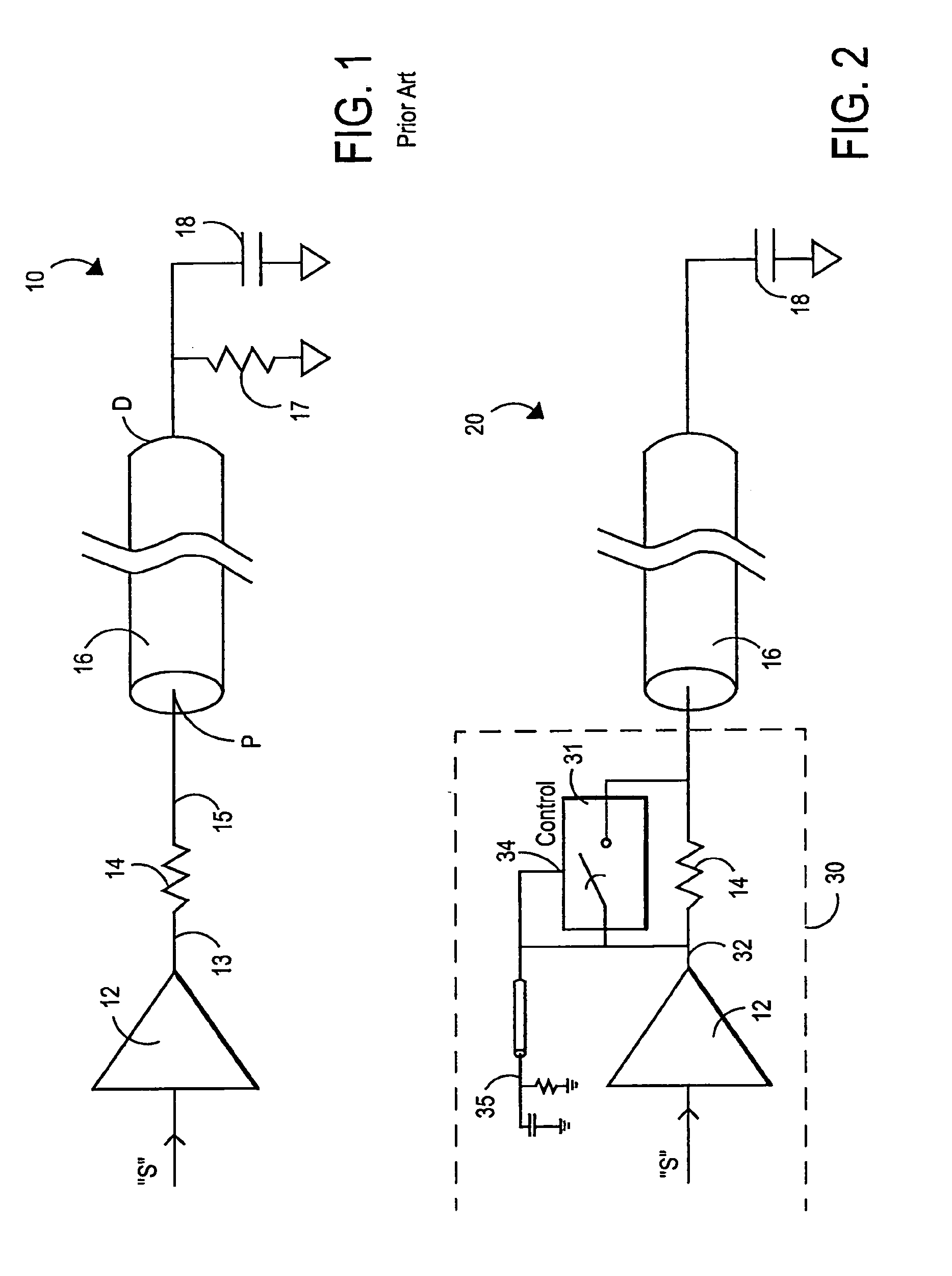
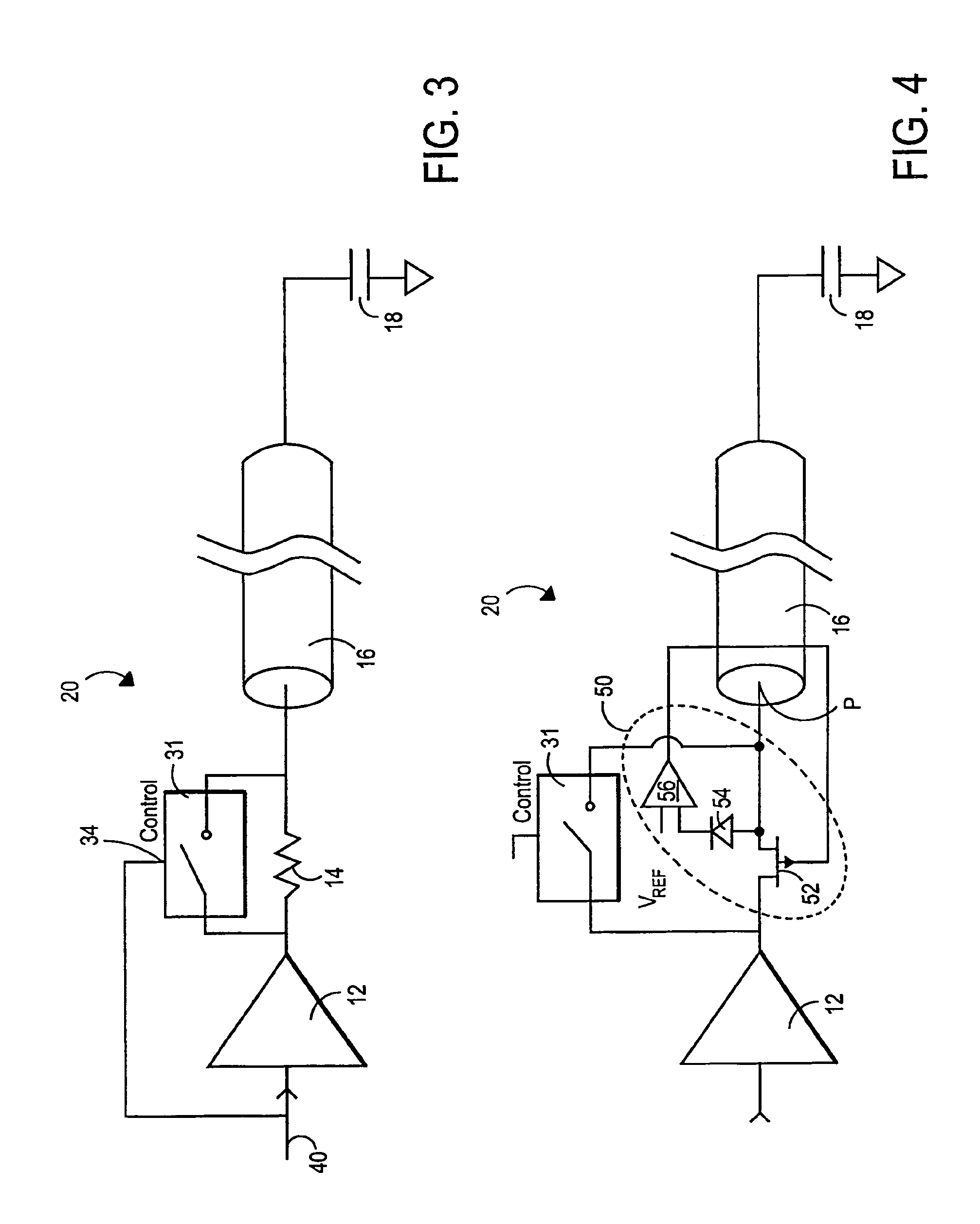
[0024]FIG. 1 depicts a prior art circuit illustrating examples of series and parallel termination schemes. As shown in FIG. 1, basic driver 12 receives a signal “S” to be transmitted. Basic driver 12 typically transmits signal “S” from its output by applying digital HIGH and LOW signals, which typically have rising edges and falling edges during transitions between HIGH and LOW values. Basic driver 12 may be any of a variety of drivers including, for example, a Gunning Transistor Logic (GTL) style driver, a tri-state driver, or a complementary pair driver. These are just examples and those of skill in the art will recognize that the principles described here are applicable to a wide variety of driving circuits and conductive elements and media that exhibit transmission line behavior in the conveyance of energy.

[0025]Basic driver 12 is connected to a first terminal 13 of the series termination 14. Series termination 14 is also known as a “source termination” and may be referred to as...


PUM


Abstract

A termination circuit changes impedance to match a transmission line impedance. The change is made after a signal driver applies a signal through the termination circuit to the transmission line but before a signal reflection returns from an end of the transmission line.

Description

TECHNICAL FIELD[0001]The present invention relates to maintaining signal integrity on transmission lines and, in particular, to dampening transmission line reflections.BACKGROUND OF THE INVENTION[0002]Transmission line termination refers to strategies or systems used to cancel, mitigate, or dampen signal reflections on transmission lines. Appropriate termination techniques also mitigate other signal integrity problems such as “ringing” oscillations and signal delays. When electronic circuitry employs high-speed components such as fast microprocessors, for example, it is particularly helpful to include proper termination impedance-matching strategies in signal transmission line designs.[0003]As the speed of digital circuits increases, a number of characteristics related to signal integrity and transmission line behavior deteriorate. It can be expected, for example, that as clock rates rise, crosstalk, the unintended influence of a line's electromagnetic field on other signals, increa...

Claims


Application Information

Patent Timeline
Patent Type & Authority Patents(United States)
IPC IPC(8): H03K19/003
CPCH04L25/0298
Inventor RAPPORT, RUSSELL
Owner TAMIRAS PER PTE LTD LLC
Why Eureka
Try Eureka