Camera device with selectable image paths

a camera device and selectable technology, applied in the field of camera devices, can solve the problems of difficult implementation of the design of the flex, unreliable, and not very practical solutions for camera phones

Inactive Publication Date: 2006-01-31
TELEFON AB LM ERICSSON (PUBL)
View PDF13 Cites 271 Cited by
  • Summary
  • Abstract
  • Description
  • Claims
  • Application Information

AI Technical Summary

Problems solved by technology

While it is technically feasible to make a display for a camera phone that can swivel, that is not a very practical solution for a camera phone.
If a flexible connector is used, the display would need to swivel

Method used


Image

  • Camera device with selectable image paths
  • Camera device with selectable image paths
  • Camera device with selectable image paths

Examples


second embodiment

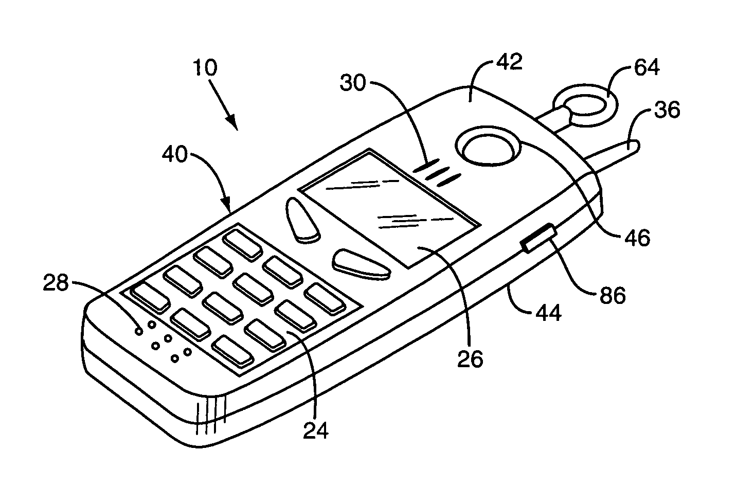
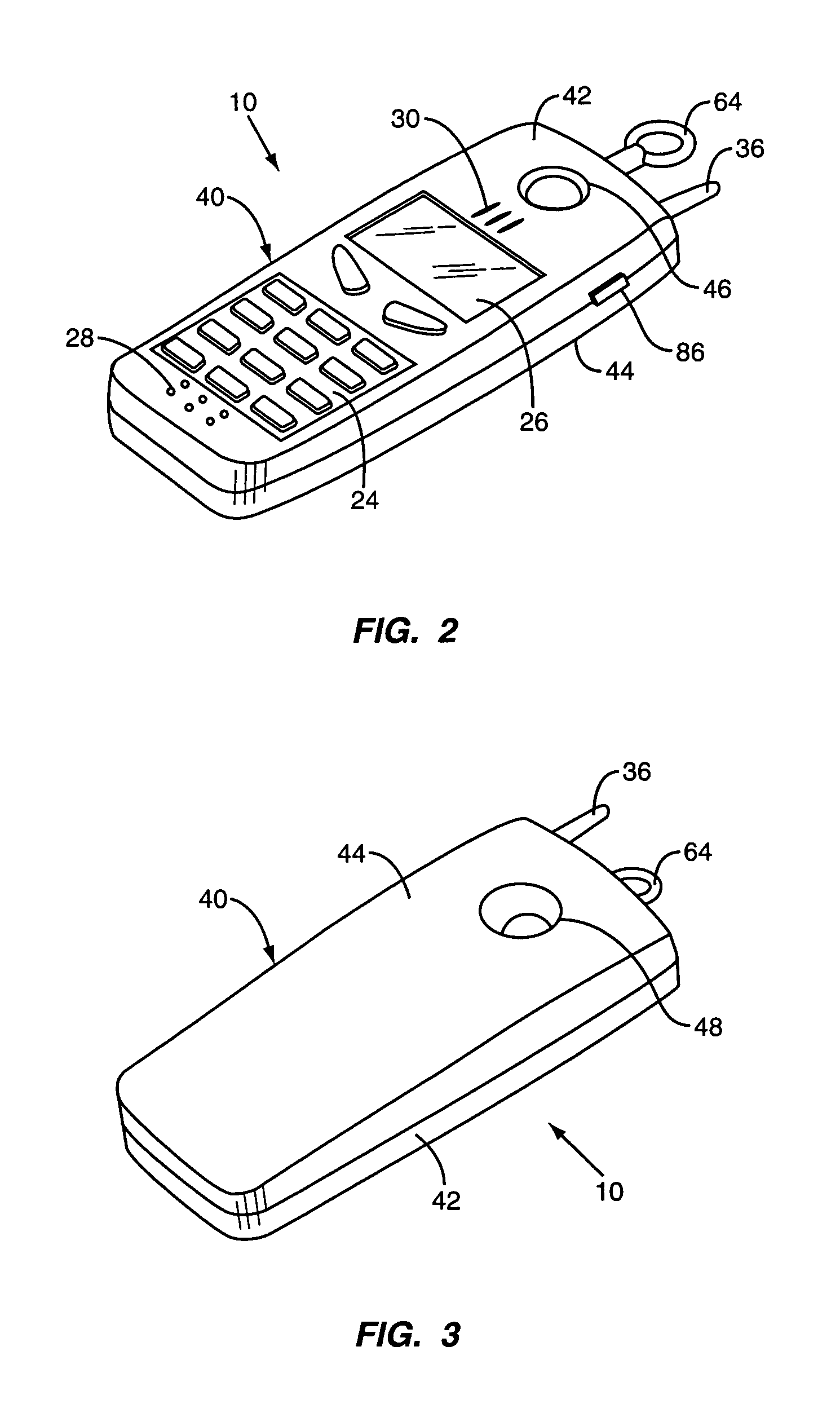
[0034]FIG. 10 is a perspective view illustrating the camera phone 10 of the present invention. The camera phone 10 of FIG. 10 is similar to the embodiment of FIGS. 1–9 and, therefore, similar reference numbers are used to indicate similar parts. In the embodiment shown in FIG. 10, a dial 65 is disposed in the front cover 42 of the camera phone 10. Dial 65 is part of a mirror assembly 52′ shown in FIG. 11. Mirror assembly 52′ includes a shaft 62′ and a double-sided reflecting mirror 56′. Dial 65 is connected to one end of shaft 62′. Reflecting mirror 56′ is mounted on shaft 62′ so as to rotate with shaft 62′. Dial 65 is turned by the user's thumb to rotate the reflecting lens 56′ between the first and second positions.

third embodiment

[0035]FIG. 12 is a perspective view of the camera phone 10. This embodiment is similar to the previous embodiments and, therefore, similar reference numbers are used to indicate similar parts. In the embodiment of FIG. 13, a sliding mirror assembly 52″ is used in place of the rotating mirror assembly 52 and 52′ of the previous embodiments. Mirror assembly 52″ comprises a shaft 62″ with a thumb pad 64″ at each end thereof and a pair of single-sided reflecting mirrors 56″. The single-sided reflecting mirrors 56″ are mounted to the shaft 62″. Reflecting mirrors 56″ are disposed at a 90° angle with respect to one another. The mirror assembly 52″ slides along the axis of the shaft 62″ as indicated by the arrows in FIG. 13 to selectively position the reflecting mirrors 56″ in the first and second optical paths, respectively.


PUM


Abstract

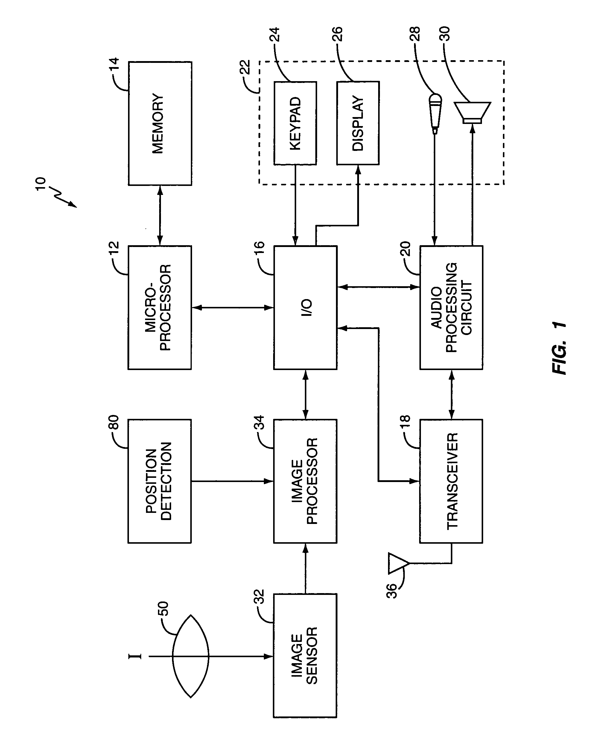
A combination mobile terminal and camera with multiple light apertures in the housing. One aperture is disposed on a front side of the housing while another aperture is disposed on a rear side of the housing. The device has an image sensor disposed within the housing for converting images formed by light directed onto the image sensor into electrical signals. The device also has a movable optical system for selectively directing light passing through one of the light apertures onto the image sensor. The device also includes an image processor coupled to an output of the image sensor for processing the electrical signals from the image sensor to produce image signals. The device also has a position detector to detect the position of the movable optics and for directing the image processor to invert the images as needed.

Description

BACKGROUND OF THE INVENTION[0001]The present invention relates generally to camera devices and, more particularly, to a camera device having first and second selectable image paths.[0002]Camera phones, which comprise a mobile, hand-held telephone and a digital camera in the same physical package, have recently been introduced to the market. At present, the development of digital camera phones is in its infancy. Wideband Code Division Multiple Access (WCDMA) and other emerging technologies will soon make it possible to send digital images and live video over wireless communication networks. These emerging technologies will spawn a new breed of camera phones that can be used for teleconferencing or for recording video that can be transmitted over the wireless communications network.[0003]When recording video, the user generally likes to see the image being recorded. In modern video cameras, the image seen through the lens of the camera is presented on a liquid crystal display. The dis...

Claims


Application Information

Patent Timeline
IPC IPC(8): H04N5/225H04N7/14
CPCH04N7/142H04N2007/145
Inventor VANCE, SCOTT LHUNT, CHARLES C
Owner TELEFON AB LM ERICSSON (PUBL)
Why Eureka
Try Eureka