Gasket seal for flanges of piping and equipment, a method for manufacturing gasket seals, and a sealing ring for a gasket seal

a technology for gasket seals and flanges, which is applied in the direction of sleeve/socket joints, fluid pressure sealed joints, joints with sealing surfaces, etc., and can solve the problems of two different thicknesses, high cost, and total failure of construction,

Inactive Publication Date: 2006-02-07
MANEGRO ADMINISTRACAO E PARTICIPACOES
View PDF17 Cites 30 Cited by
  • Summary
  • Abstract
  • Description
  • Claims
  • Application Information

AI Technical Summary

Benefits of technology

[0015]One can see that the present invention presents a solution by which the centralization ring is fitted into the sealing ring without the need to be separated and then welded.

Problems solved by technology

This construction, however, has the disadvantage of two different thicknesses.
This variation in thermal expansion between the parts of different thickness of the gasket causes cracks that may eventually lead to breakage thereof and total failure.
In addition to the serious problem of premature failure, these constructions, with or without recess, are very expensive, since they require machining and great wastage of material.
However, one can see that methods of the prior art for fitting centralization rings on sealing rings have the drawback of involving steps of separating the centralization rings and then welding them.

Method used


Image

  • Gasket seal for flanges of piping and equipment, a method for manufacturing gasket seals, and a sealing ring for a gasket seal
  • Gasket seal for flanges of piping and equipment, a method for manufacturing gasket seals, and a sealing ring for a gasket seal
  • Gasket seal for flanges of piping and equipment, a method for manufacturing gasket seals, and a sealing ring for a gasket seal

Examples


Embodiment Construction

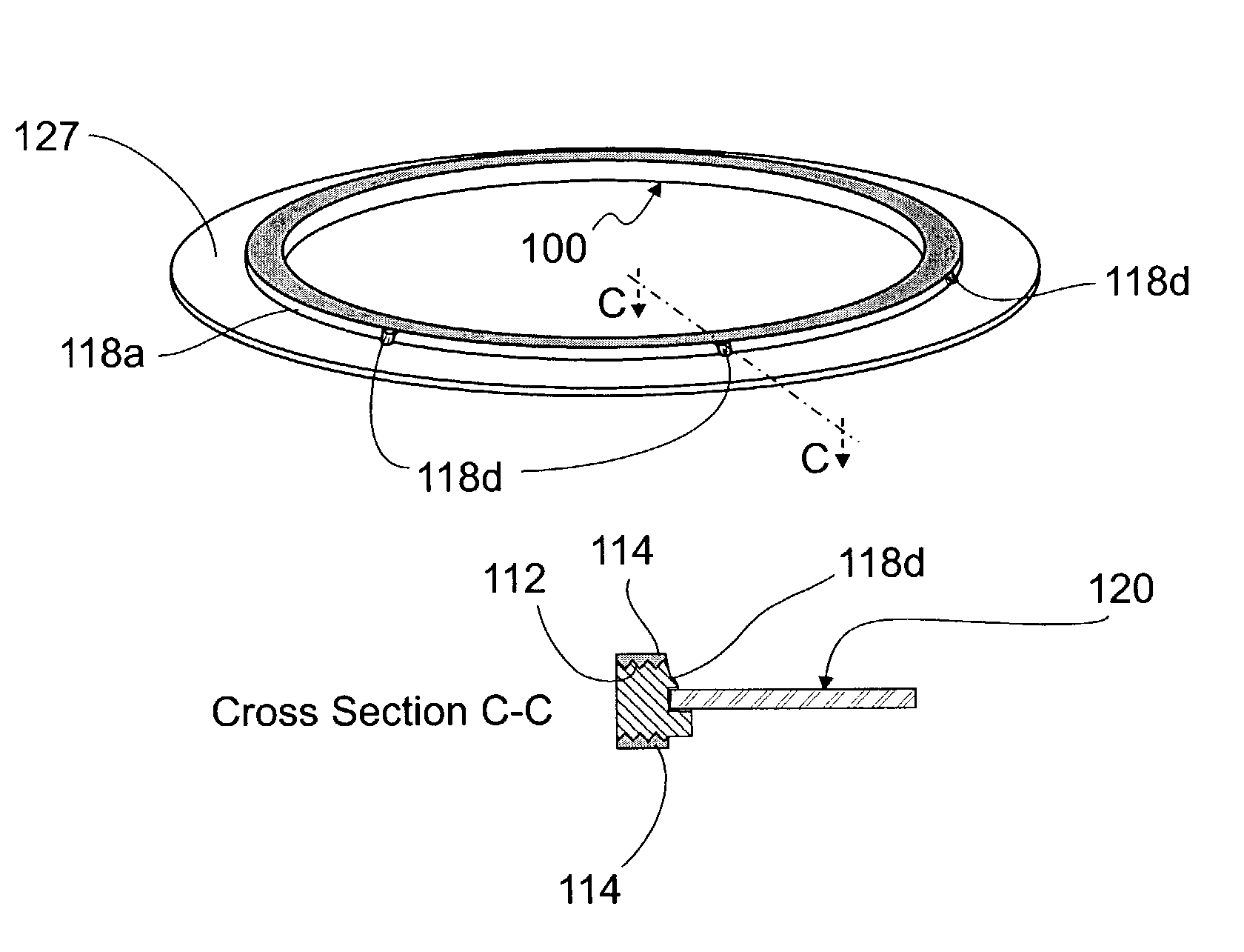
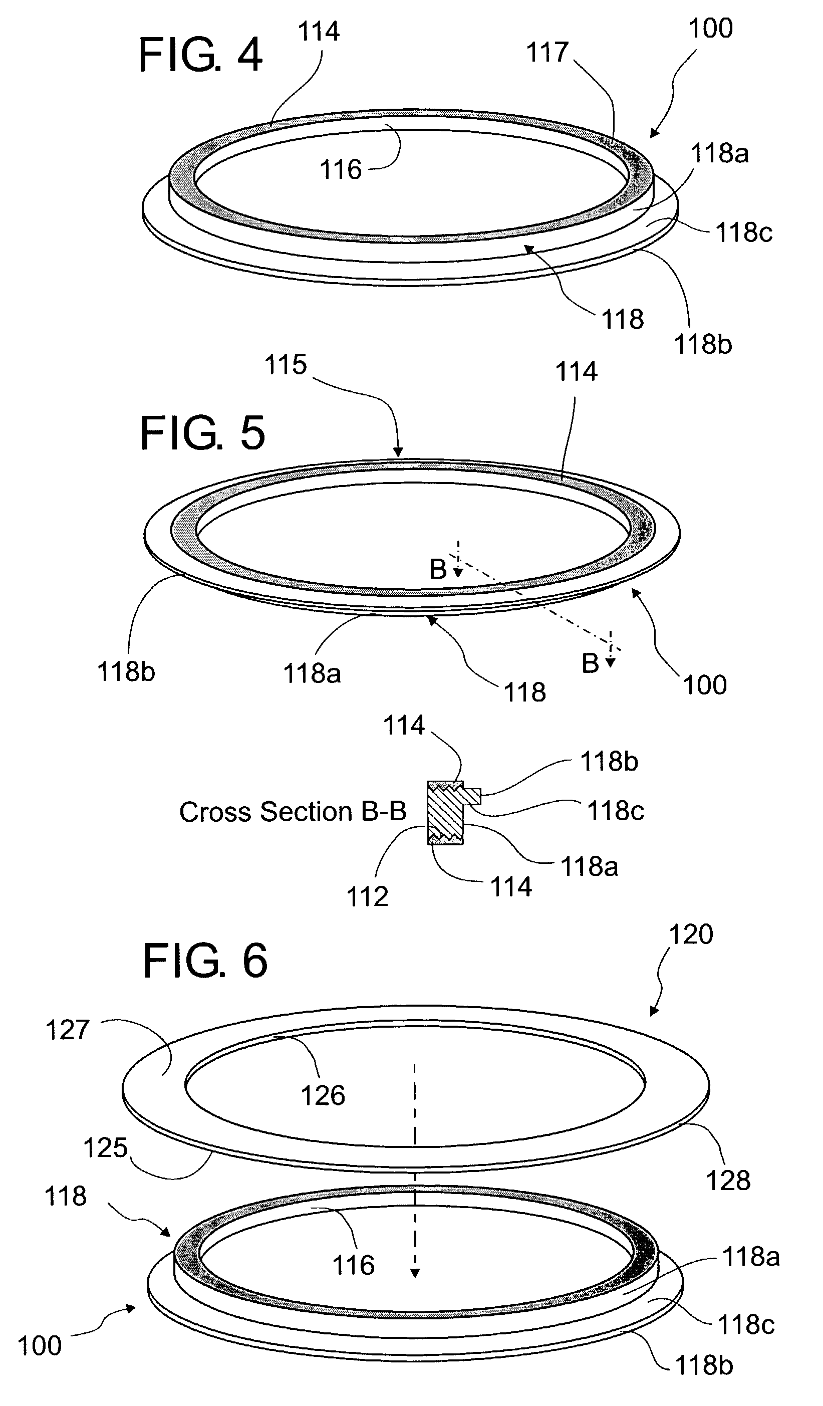
[0026]As illustrated in FIGS. 4 and 5, the present invention may be embodied in a sealing ring 100 to be inserted into flanges of piping and equipment, so as to make the sealing of these piping and equipment when these flanges are tightened against each other (usually by means of nuts and bolts). The ring 100 of this embodiment comprises an outer contour surface 118, an inner contour surface 116, a lower surface 115 and an upper surface 177. The outer contour surface 118 comprises a substantially L-shaped cross-section comprising an innermost portion 118a, an outermost portion 118b extending axially, and a radial portion 118c interconnecting the inner and outer portions. The inner contour surface 116 defines a central opening coinciding with the openings of the flanges of the piping and equipment (not shown). The lower surface 115 and upper surface 117, shown in FIGS. 4 and 5, respectively, consist of respective lower and upper prolongations of the outer contour surface 118 and inne...


PUM


Abstract

A gasket seal for piping and equipment flanges comprises a sealing ring and a centralization ring, preferably concentric rings made of a metallic alloy. The sealing ring has an outer contour surface having a substantially L-shaped cross-section comprising an innermost portion and an outermost portion extending axially and a radial portion interconnecting the inner and the outer portions. The centralization ring has an inner contour surface defining a central opening, substantially coincident with the innermost portion of the outer contour surface of the sealing ring, so that the latter can be fitted into the opening as far as the radial portion of its outer contour surface. A deformation is made on the innermost portion of the outer contour surface of the sealing ring, forming a projection, whereby the centralization ring can be retained between the projection and radial portion without the centralization ring needing to be separated and then welded.

Description

[0001]This invention constitutes a gasket seal for application in flanges of piping and equipment, a method for manufacturing gasket seals, and sealing rings for gasket seals.DESCRIPTION OF THE PRIOR ART[0002]A number of metallic and semi-metallic seals have been developed for piping and equipment. The most usual ones are spiral gaskets, flat metallic gaskets, serrated metallic gaskets with graphite or PTFE coating or (“Camprofile”), graphite gaskets with metallic inserts and gaskets with metallic jackets, which are installed between the flanges when the latter are tightened against each other (usually by means of sets of bolts and nuts). In order to achieve high resistance to pressure and good seating to the flange surfaces, the gaskets are formed of different combinations of materials and shapes.[0003]Among the gaskets of the prior art, the metallic serrated gaskets with a graphite or PTFE coating have achieved a good performance in sealing piping and equipment. As will be describ...

Claims


Application Information

Patent Timeline
Patent Type & Authority Patents(United States)
IPC IPC(8): F16L17/00F16J15/06F16L23/18H02G9/06H02G15/013
CPCF16J15/061H02G15/013H02G9/06F16L23/18
Inventor VEIGA, JOSE CARLOS C.
Owner MANEGRO ADMINISTRACAO E PARTICIPACOES
Why Eureka
Try Eureka