Panel mounted electrical connector system

a technology of electrical connectors and mounting brackets, which is applied in the direction of coupling device connections, coupling device details, incorrect coupling prevention, etc., can solve the problems of affecting the quality of the electrical connection, damage to the housing of the connector, and the terminals that are fragile in the housing

Inactive Publication Date: 2006-02-07
MOLEX INC
View PDF9 Cites 12 Cited by
  • Summary
  • Abstract
  • Description
  • Claims
  • Application Information

AI Technical Summary

Problems solved by technology

Quite often, the mating of a panel mounted electrical connector to another connector or circuit component is carried out under blind mating conditions such that precise alignment of the panel mounted connector with the other connector cannot be assured.
Attempts to forcibly blind mate improperly aligned electrical connectors can damage the housings of the connectors, the fragile terminals mounted in the housings or, in some instances, even the panels to which the connectors are mounted.
Improper alignment also may prevent complete mating, thereby negatively affecting the quality of the electrical connection.
Many such connectors have been fairly complex multi-component structures which may even be manufactured separately from the electrical connector and require assembly and installations.

Method used


Image

  • Panel mounted electrical connector system
  • Panel mounted electrical connector system
  • Panel mounted electrical connector system

Examples


Embodiment Construction

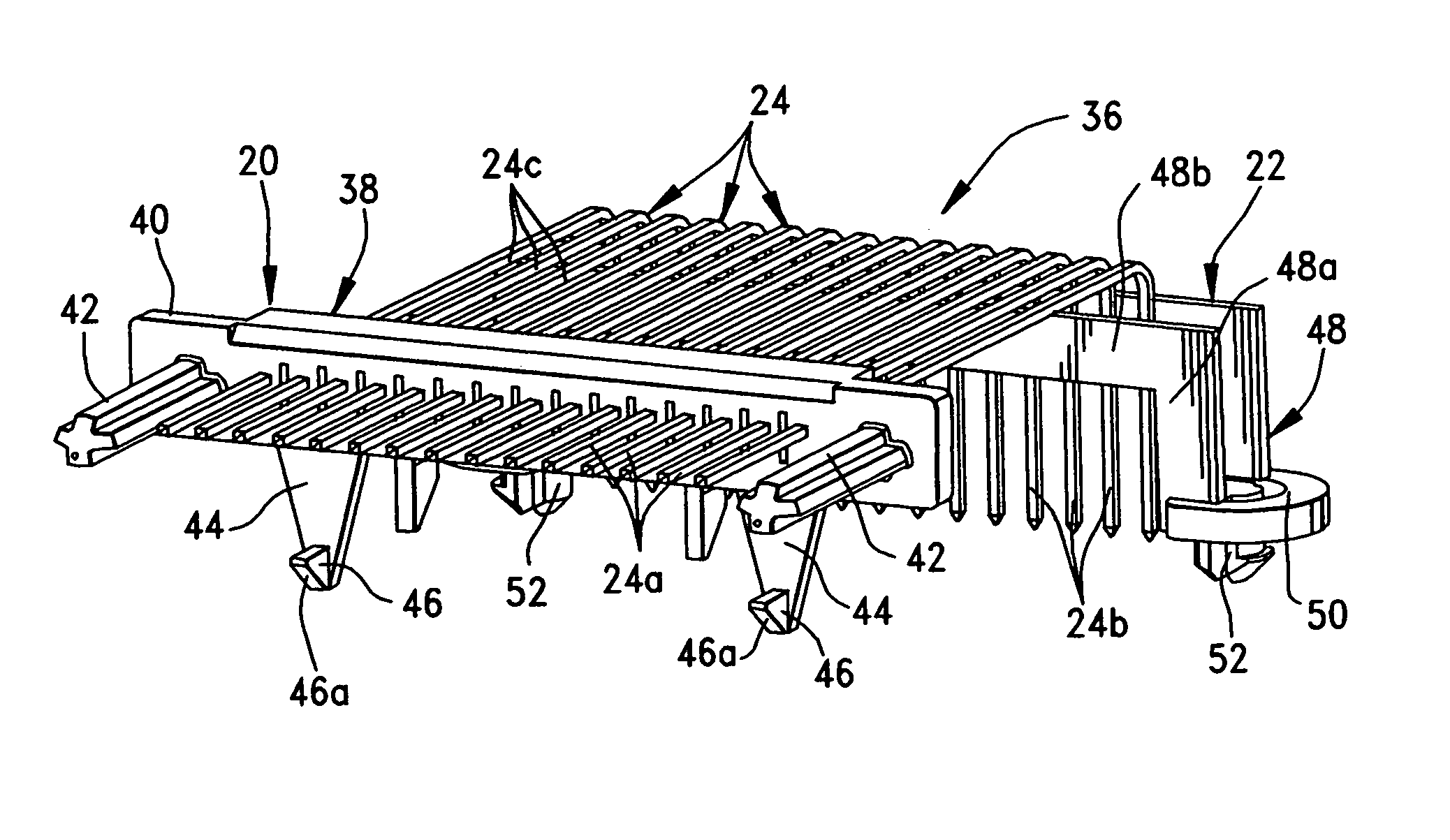
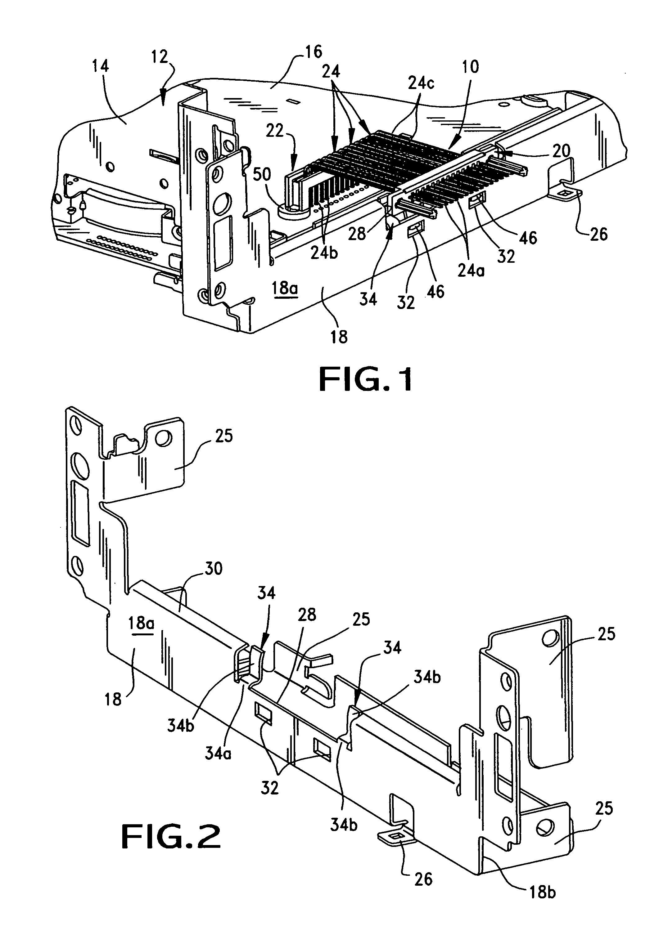
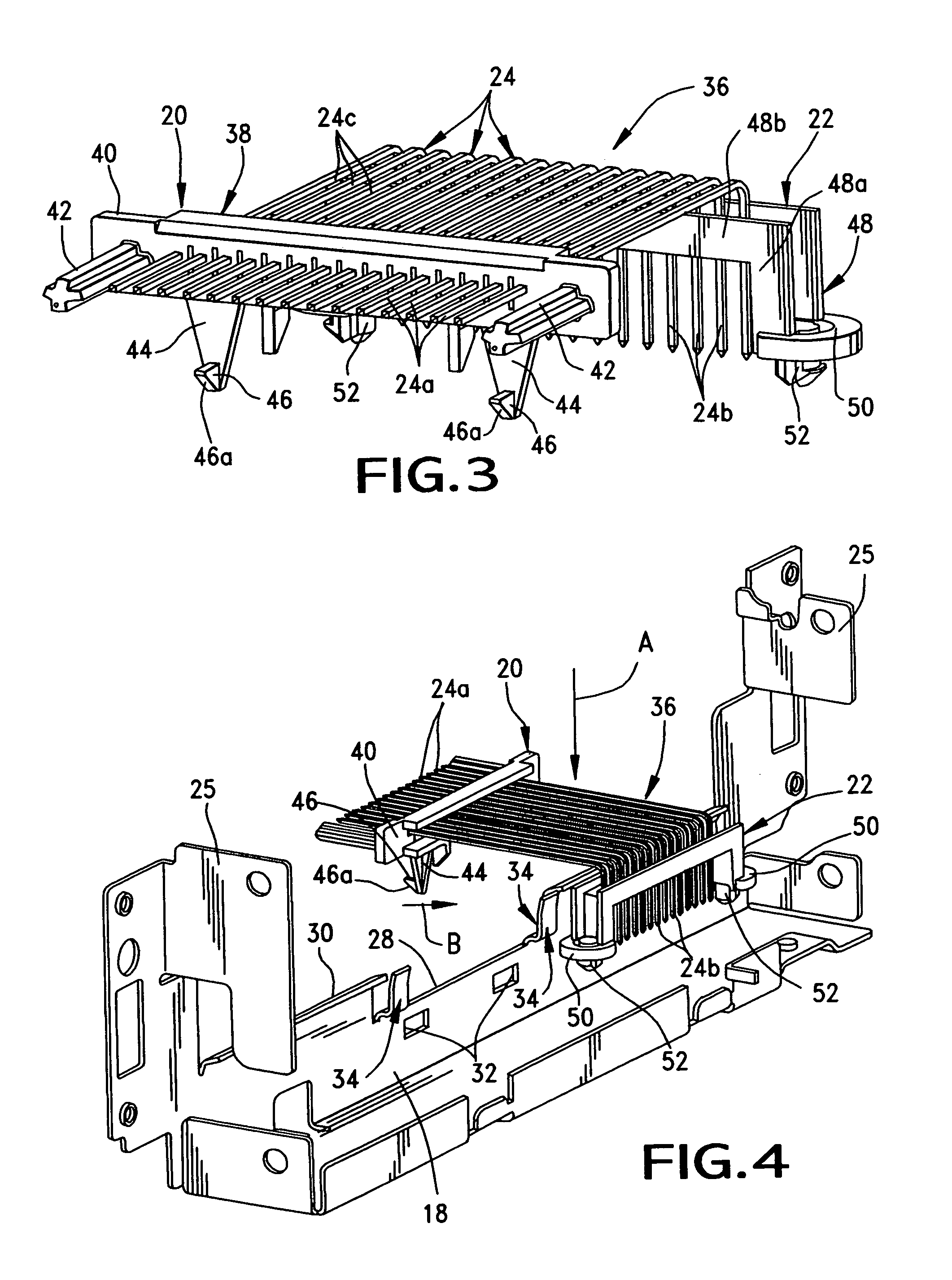
[0019]Referring to the drawings in greater detail, and first to FIG. 1, the invention is embodied in an electrical connector system, generally designated 10, which is part of an overall chassis, generally designated 12, which is part of an automotive radio assembly. The chassis includes a rear frame 14 which mounts a generally horizontal printed circuit board 16. A front panel 18 is mounted to frame 14 forwardly of the printed circuit board. Connector assembly 10 includes a panel mounted electrical connector, generally designated 20, which is mounted on and through panel 18, along with a header connector, generally designated 22, which is mounted on top of printed circuit board 16. A plurality of terminals, generally designated 24, extend between panel mounted connector 20 and header connector 22.

[0020]FIG. 2 shows panel 18 in greater detail. The panel includes a plurality of various mounting flanges 25 which project rearwardly thereof for securing the panel to rear frame 14 (FIG. 1...


PUM


Abstract

An electrical connector system includes a panel having a front face, a rear face, a hole through which a connector can mate with a complementary connecting device at the front face of the panel, and an opening spaced from the hole. A connector includes a dielectric housing insertable into the hole in the panel and mateable with the complementary connecting device at the front face of the panel. The housing mounts a plurality of terminals and is sized smaller than the hole to allow for controlled floating movement of the connector relative to the panel. At least one locking arm projects from the housing and has a locking protrusion for engagement in the opening in the panel to prevent excessive movement of the connector in a direction generally parallel to the panel. The opening is larger than the locking protrusion to allow for said controlled floating movement of the connector relative to the panel. At least one flange projects from the rear face of the panel over a rear portion of the connector housing to prevent excessive movement of the connector in a direction generally perpendicular to and rearwardly of the panel. The terminals have flexibly stiff elongated portions projecting rearwardly of the housing to a fixed support structure for supporting the housing generally centrally in the hole in the panel but allowing said controlled floating movement of the connector relative to the panel.

Description

FIELD OF THE INVENTION[0001]This invention generally relates to the art of electrical connectors and, particularly, to a floating panel mounting system for electrical connectors.BACKGROUND OF THE INVENTION[0002]It is known to provide a variety of systems for mounting an electrical connector on or in a panel, such as at a rear side of a panel. Panel mounted electrical connectors usually include a non-conductive or dielectric housing having a plurality of electrically conductive terminals mounted therein. The housing also includes some form of means for mounting the connector to a panel. The panel mounted connector may be mounted to a rear side of a panel, for instance, and is mateable with other electrical apparatus, such as another connector at a front side of the panel. The other connector, in turn, may be mounted to a second panel, a circuit board, a cable or discrete electrical wires.[0003]Quite often, the mating of a panel mounted electrical connector to another connector or cir...

Claims


Application Information

Patent Timeline
Patent Type & Authority Patents(United States)
IPC IPC(8): H01R13/64H01R13/631H01R13/74
CPCH01R13/6315H01R13/74
Inventor MARGULIS, YANLUTHY, JOHN S.SAMIEC, KAREN
Owner MOLEX INC
Why Eureka
Try Eureka