Moisture detection and location system

a moisture detection and location technology, applied in the direction of fluid tightness measurement, instruments, electric signalling details, etc., can solve the problems of unwanted moisture may nevertheless intrude into the structure, and unfavorable structural moisture intrusion into the building envelop

Inactive Publication Date: 2006-02-07
AMACHER MARK
View PDF33 Cites 99 Cited by
  • Summary
  • Abstract
  • Description
  • Claims
  • Application Information

AI Technical Summary

Benefits of technology

[0014]The system includes a plurality of moisture sensors, with at least one moisture sensor being located at each location to be monitored for moisture. Such collection of sensors may be located within a single structure, or disposed about multiple structures. Each moisture sensor is activated upon the presence of moisture at the respective location of the sensor, causing the sensor to generate a signal. Such a signal may be an audible signal, a visual signal, or both an audible and visual signal from the sensor itself, or such a signal may be an electric signal or a wireless signal for receipt by other system components as will be described hereinbelow. In one embodiment, a moisture sensor may include at least two electrically conductive leads, located relative to each other so that moisture near or between the leads completes an electrical circuit. In such an embodiment, the leads may be configured in a nearly flat plane, so as to be capable of being attached in small or narrow spaces, and the leads may be carried by a pliable substrate, allowing the sensor to be conformed to the particular portion of the structure upon which it is attached.
[0015]The system may also include at least one receiver that is in communication with the moisture sensors, although more than one such receiver may be used at once, depending upon the requirements of the particular application. The receiver will provide a remote identification of the location of any moisture sensor that becomes activated by the presence of moisture. Such identification may be by an audible identifying alarm, or by a visual identifier such as a visual display panel. Such a receiver may be located within a single structure being monitored for moisture, may be located within one of several structures when the system is used in a plurality of structures, or may be remote to any and all structures being monitored for moisture.

Problems solved by technology

Despite advancements in materials and techniques for constructing and fabricating structures, it has been found that unwanted moisture may nevertheless intrude into a structure.
However, moisture may nevertheless intrude beyond the envelope into the structure.
Structural moisture intrusion into the building envelope can be quite damaging.
Even small moisture quantities that have intruded beyond the exterior cladding or roofing of a structure promote the development and progression of wood-destroying organisms, rust, or other destructive and detrimental processes.
The troubles caused by moisture intrusion are often exacerbated because the moisture intrudes only to unseen, interior portions of the structure, such as the interior portions of exterior walls in a building, and it is there, undetected, that the destructive and detrimental processes develop and grow.
The structural damage resulting from such processes often cannot be detected until such damage has progressed so far, for so long, that its destruction progresses beyond the unseen, interior portions of the structure into adjacent visible portions of the structure.
Such destructive progression exacerbates both the degree of damage and the costs of repairs to the structure.
As an example of such harmful effects, it has been discovered that moisture intrusion into a building often occurs at penetrations to the exterior cladding of the building, such as windows, doors, exterior lighting fixtures, exterior electrical outlets, side ventilations from dryers, and the like.
As a further illustrative example, moisture intrusion has been found to be a problem with buildings clad in synthetic stucco.
However, at stucco building wall surface penetrations, including windows, doors, exterior electrical outlet penetrations, and the like, the juncture of the terminating edge of the synthetic stucco exterior cladding with the adjoining edge of the penetrating component is susceptible to the intrusion of moisture.
The exemplified problem, however, is not confined to buildings utilizing exterior synthetic stucco cladding, and indeed has been found to occur in buildings using masonry products such as brick veneer, buildings using wood siding, and in other buildings using different materials and techniques for exterior cladding.
The problem of detecting and locating the intrusion of moisture beyond the exterior cladding of a structure is quite difficult to solve.
Furthermore, the spaces provided in such structures for disposition of system detection and location components at locations susceptible to such moisture intrusion are quite small—for example, moisture can intrude at the juncture of a exterior building cladding system and a window frame, which involves the space of only a small fraction of an inch.
Any such system also must be able to detect quite small quantities of moisture, as it has been found that even small quantities are nevertheless sufficient for the promotion and development of destructive processes, particularly considering that such small quantities may be located within the structural system at a location that does not allow for escape or evaporation.
However, visual detection often cannot be provided, because moisture intrusion often stops within walls, window systems, door systems, and so forth, and it is there that the rot or rust begins; such a system must provide for detection and location notwithstanding the absence of visual indicia of such moisture intrusion.
At the same time, though, such a system must require little to no maintenance, as it is the sense of security promoted by installation of such a system that is the motivation on the part of the responsible party for such installation, and many of such system components may be built into such a structure during original construction and will not thereafter be accessible for later service.

Method used


Image

  • Moisture detection and location system
  • Moisture detection and location system
  • Moisture detection and location system

Examples


Embodiment Construction

[0032]Reference now will be made in detail to the presently preferred embodiments of the invention, one or more examples of which are illustrated the drawings. Each example is provided by way of explanation of the invention, and is not meant as a limitation of the invention. For example, features illustrated or described as part of one embodiment can be used on another embodiment to yield yet another embodiment. It is intended that the present application includes such modifications and variations as come within the scope and spirit of the invention.

[0033]The same numerals are used to refer to the same features throughout the drawings and the text that follows.

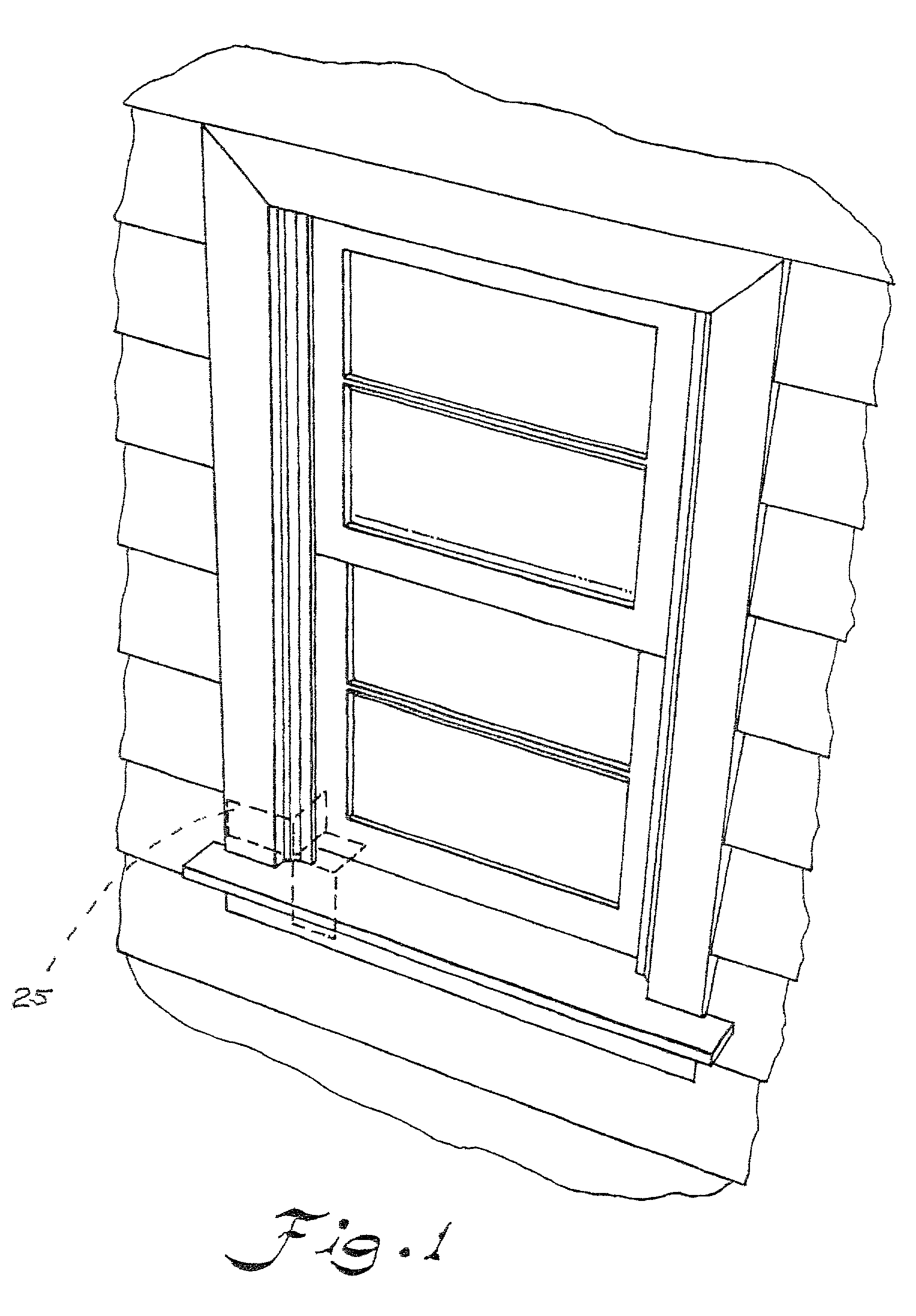
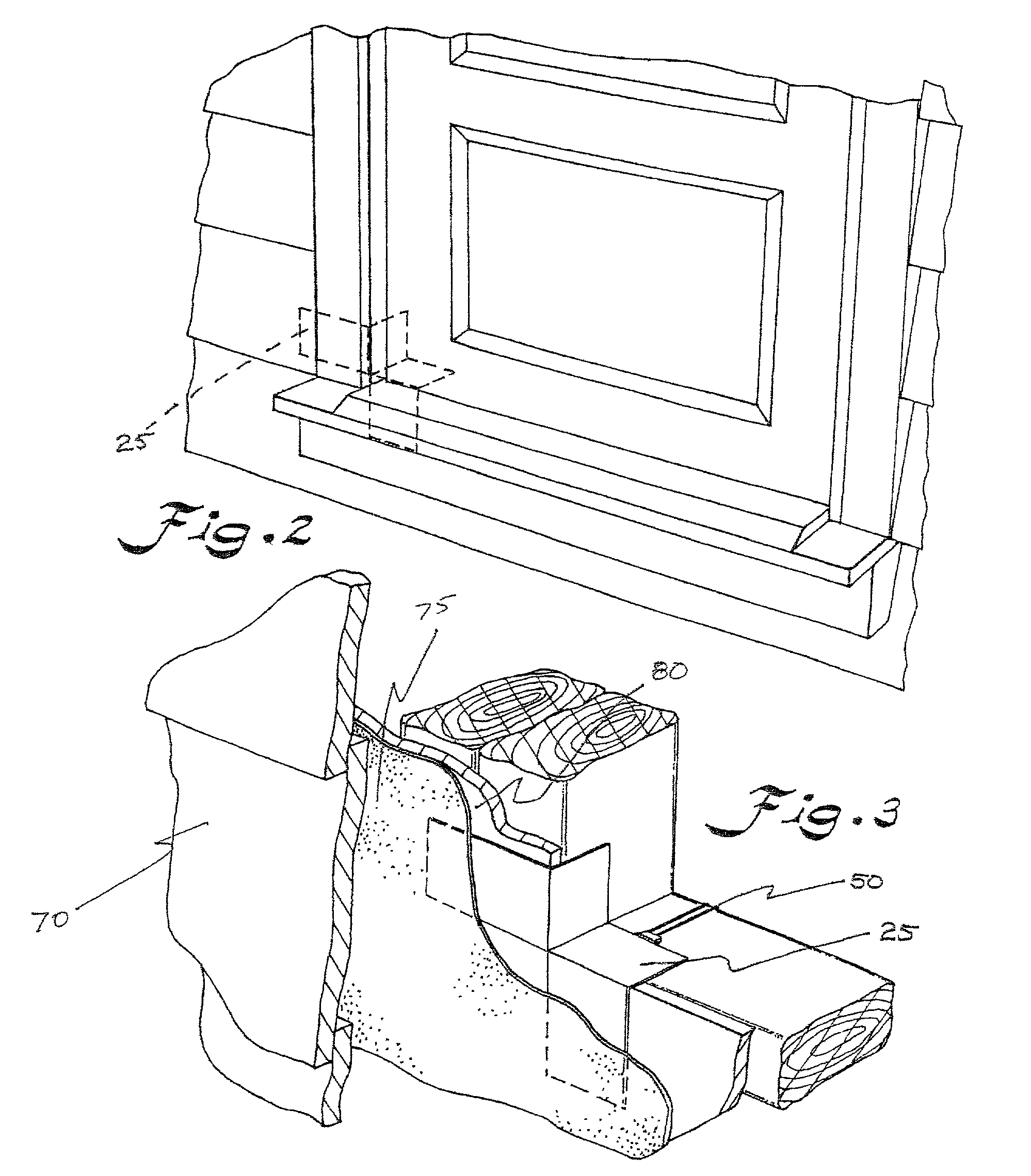
[0034]Referring to the appended Figures in general, a system 20, particularly a moisture detection and location system, according to the invention is illustrated. System 20 is not limited in its field of use, and has usefulness in any environment in which it is desired to separately detect and locate moisture at a plurality of...


PUM


Abstract

A system is provided to monitor for moisture at separate locations interior to exterior structure cladding. The system includes a plurality of moisture sensors, at least one of which is disposed at each location to be monitored. Upon activation by the presence of moisture at its respective said location, the moisture sensor generates a signal. The system may also include a receiver in communication with the moisture sensors, to provide an identifier of the location of an activated moisture sensor. The moisture sensors and receiver may communicate via wiring, or wirelessly. The system so provided may be disposed within a single structure, or within a plurality of structures, with the receiver disposed within such a structure or remote to any such monitored structure.

Description

FIELD OF THE INVENTION[0001]The present invention relates to a monitoring system for detection and location of moisture at multiple, separate locations about structures. More specifically, the present invention provides a moisture detection and location system with multiple sensors that may be in communication with a receiver to provide an identifier of the location of detected moisture, and may be deployed in a single structure or multiple structures.BACKGROUND OF THE INVENTION[0002]Despite advancements in materials and techniques for constructing and fabricating structures, it has been found that unwanted moisture may nevertheless intrude into a structure.[0003]A structure such as a residential or commercial building may be considered to have an exterior building envelope that includes the exterior cladding of the walls and the roof. The exterior wall cladding may be brick masonry veneer, synthetic or masonry stucco, fiberboard siding, or other materials, while the roof may includ...

Claims


Application Information

Patent Timeline
Patent Type & Authority Patents(United States)
IPC IPC(8): G08B21/00G08B21/20
CPCG08B21/20
Inventor AMACHER, MARK
Owner AMACHER MARK
Why Eureka
Try Eureka