Side airbag device

a side airbag and airbag technology, applied in the direction of pedestrian/occupant safety arrangement, vehicular safety arrangment, vehicle components, etc., can solve the problems of airbag inflation and destabilization of the inflation state of the airbag, and achieve the effect of reducing the impa

Inactive Publication Date: 2006-02-14
TOYODA GOSEI CO LTD
View PDF13 Cites 109 Cited by
  • Summary
  • Abstract
  • Description
  • Claims
  • Application Information

AI Technical Summary

Benefits of technology

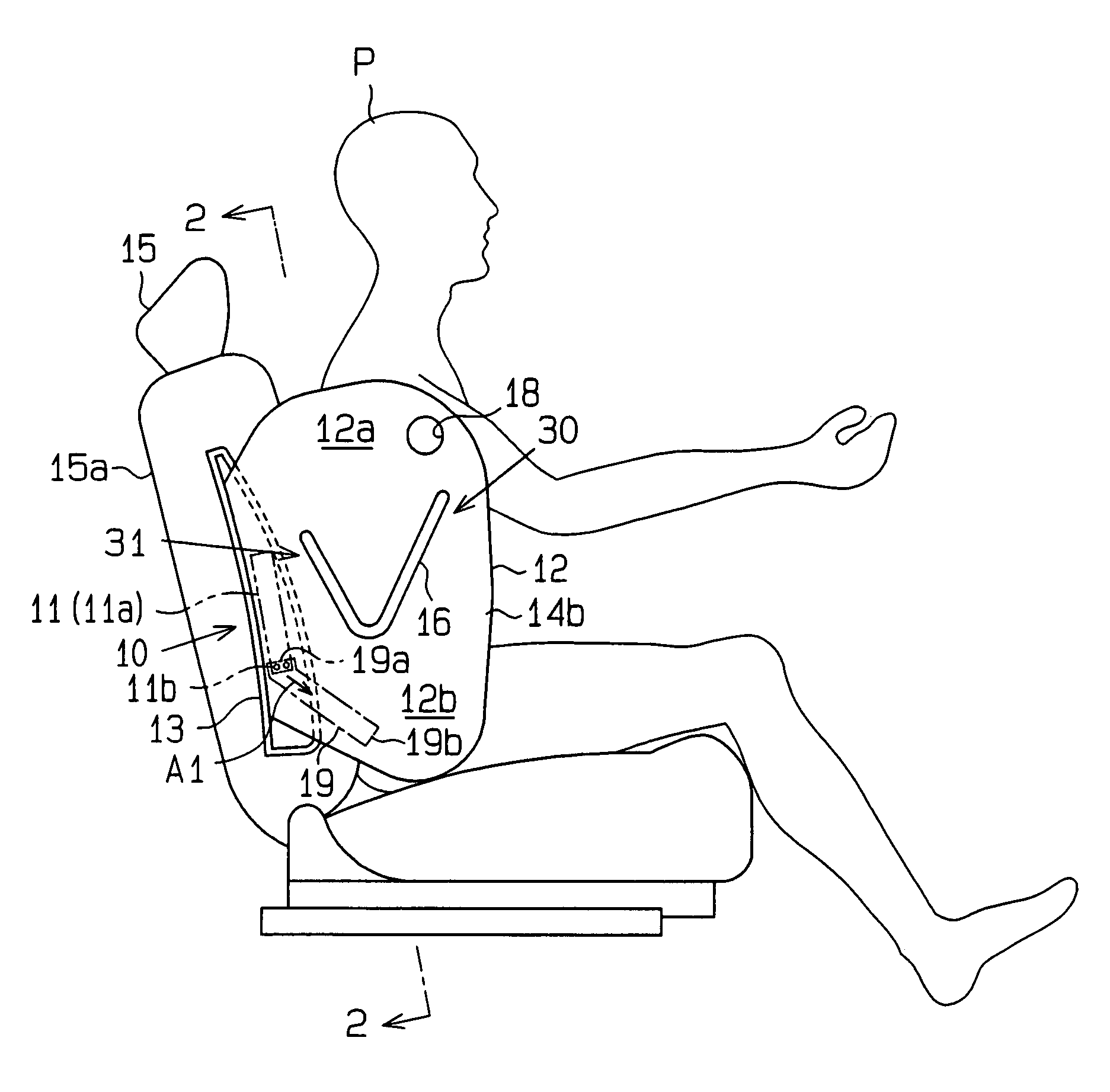
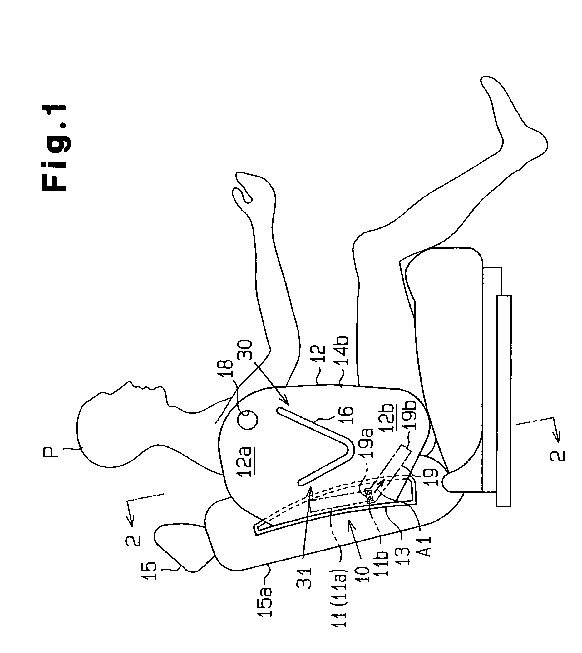
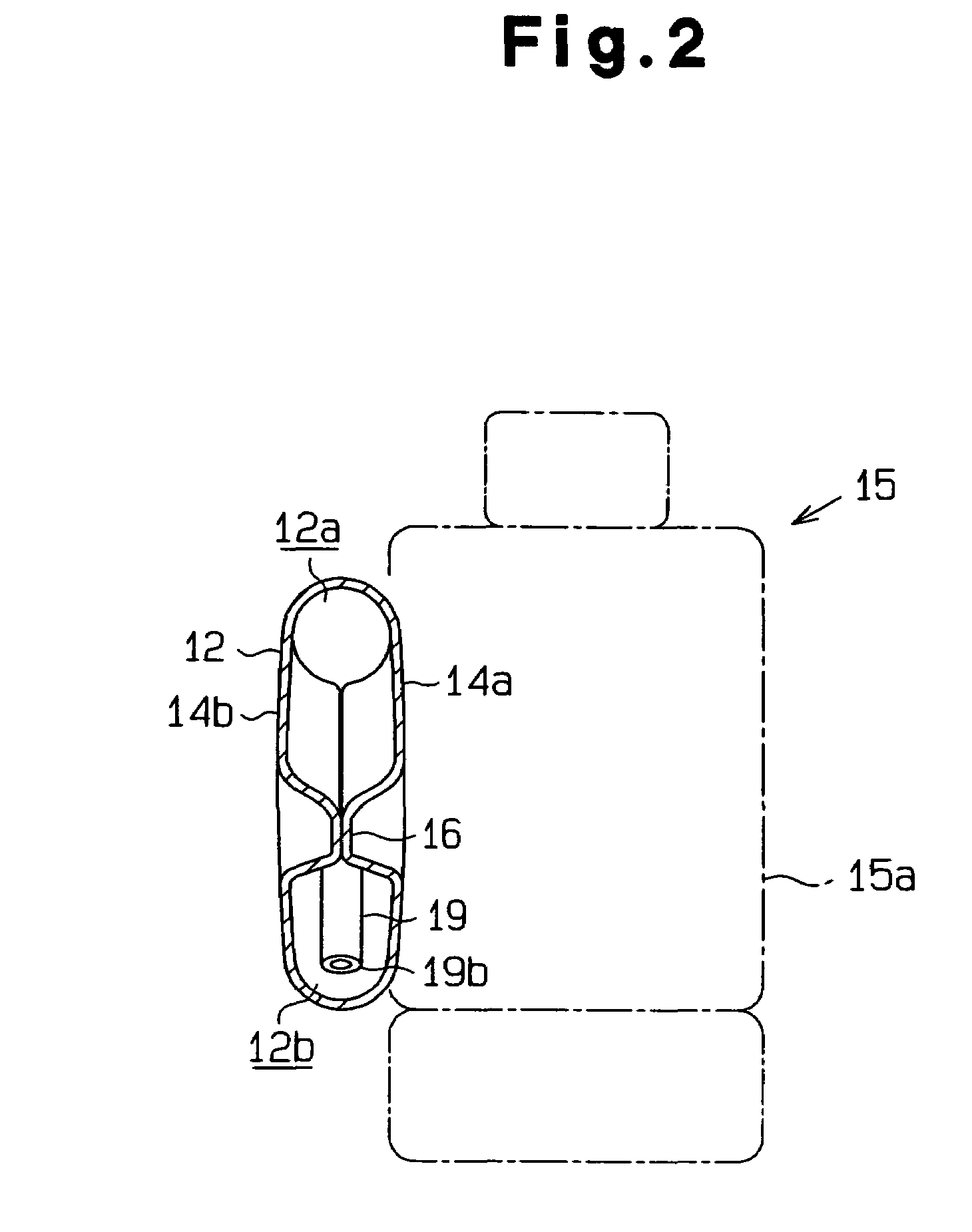
[0008]The present invention provides an air bag device, which may be mounted on the backrest of a vehicle seat. The air bag device includes a gas discharging means arranged in the backrest for discharging gas, an air bag including an upp

Problems solved by technology

Additionally, in the device, when an obstacle is placed in the inflation range of the air bag, such as on the surface of the seat, the air bag may be inflated in a state where the obstacle gets

Method used


Image

  • Side airbag device
  • Side airbag device
  • Side airbag device

Examples


modified examples

[0168]The fourth embodiment may be modified, as described below.

[0169]The upper inflation portion 425 of the air bag 418 may be omitted. In this case, it is desirable that a vent hole 431 be arranged, for example, at a distal end portion of the main portion 424.

[0170]When the backrest 413 of the seat 411 has enough accommodation space, at least one of the folding of the upper inflation portion 425 and the folding of the distal end portion 426b of the lower inflation portion 426 may be omitted.

[0171]The case 419 may be omitted and the air bag device 414 may be mounted on the backrest 413 of the seat 411.

[0172]The air bag 418 may be formed by sewing a sheet of fabric in a bag-like manner.

[0173]The connector 427 of the air bag 418 may be formed by bonding or fusing, or using a fastener instead of sewing the base fabrics. Further, the connector 27 may be formed by arranging a base fabric between the two base fabrics 423a and 423b.

[0174]The connector 427 of the air bag 418 may be omitte...


PUM


Abstract

A side air bag device includes an inflator arranged in a backrest of a seat for discharge gas, an air bag having an upper chamber and a lower chamber which are each inflated by discharging gas, and an impact reducing means reducing means ror reducing impact that is applied to a passenger when the air bag contacts the passenger during inflation of the air bag.

Description

BACKGROUND OF THE INVENTION[0001]The present invention relates to an air bag device, which operates when impact that is greater than or equal to a predetermined value is applied to the body of, for example, a vehicle, to protect passengers from the impact. More particularly, the present invention relates to a vehicle seat in which a side air bag device is installed.[0002]Such a side air bag device includes an air bag that is inflated between a sidewall of a vehicle body and a passenger who is sitting in a vehicle seat arranged in the vehicle. The side air bag device includes an inflator that discharges inflation gas into the air bag. When the impact applied to the sidewall of the vehicle body is greater than or equal to a predetermined value, the inflator discharges inflation gas to inflate the air bag instantaneously. As a result, the effect of the impact on the passenger is absorbed.[0003]For example, Japanese Laid-Open Patent Publication No. 2000-177527 proposes a side air bag de...

Claims


Application Information

Patent Timeline
IPC IPC(8): B60R21/16B60R21/20B60R21/207B60R21/231B60R21/233B60R21/2338B60R21/2346B60R21/237B60R21/239
CPCB60R21/207B60R21/23138B60R21/233B60R21/2338B60R21/2346B60R21/237B60R2021/23382B60R21/239B60R2021/23146B60R2021/23316B60R2021/23324B60R2021/23332
Inventor TANASE, TOSHINORIMIZUNO, YOSHIOKOYAMA, TORU
Owner TOYODA GOSEI CO LTD
Why Eureka
Try Eureka