Passive method for obtaining controlled drainage from a vessel

a technology of controlled drainage and passive method, which is applied in the direction of sewer systems, marine site engineering, construction, etc., can solve the problems of increasing installation, maintenance and operating costs, electrical pumps not operating if power is supplied, and actual flow rates seldom match the desired drainage ra

Inactive Publication Date: 2006-02-14
FLEEGER HOWARD W
View PDF10 Cites 16 Cited by
  • Summary
  • Abstract
  • Description
  • Claims
  • Application Information

AI Technical Summary

Problems solved by technology

Pumps can be used to manage flow rates from the reservoir, but these increase installation, maintenance and operating costs.
In addition, electrical pumps will not operate if power is lost, as often happens during periods of rain because of lightning, winds, automobile accidents and other weather-related causes.
This leads to two seemingly contradictory problems, in which actual flow rates seldom match the desired drainage rate.
The result is that when draining small rainfalls from these small drainage basins, the actual drainage rates are higher than desired, because the orifice is too large to restrict the flow to the desired rate.
The converse problem is seen when larger rainfalls are experienced.
The result is that the detainment systems must be oversized to hold extra water because the drainage rates are usually less than allowed.
Oversizing the system increases equipment, transportation and installation costs.

Method used


Image

  • Passive method for obtaining controlled drainage from a vessel
  • Passive method for obtaining controlled drainage from a vessel
  • Passive method for obtaining controlled drainage from a vessel

Examples


Embodiment Construction

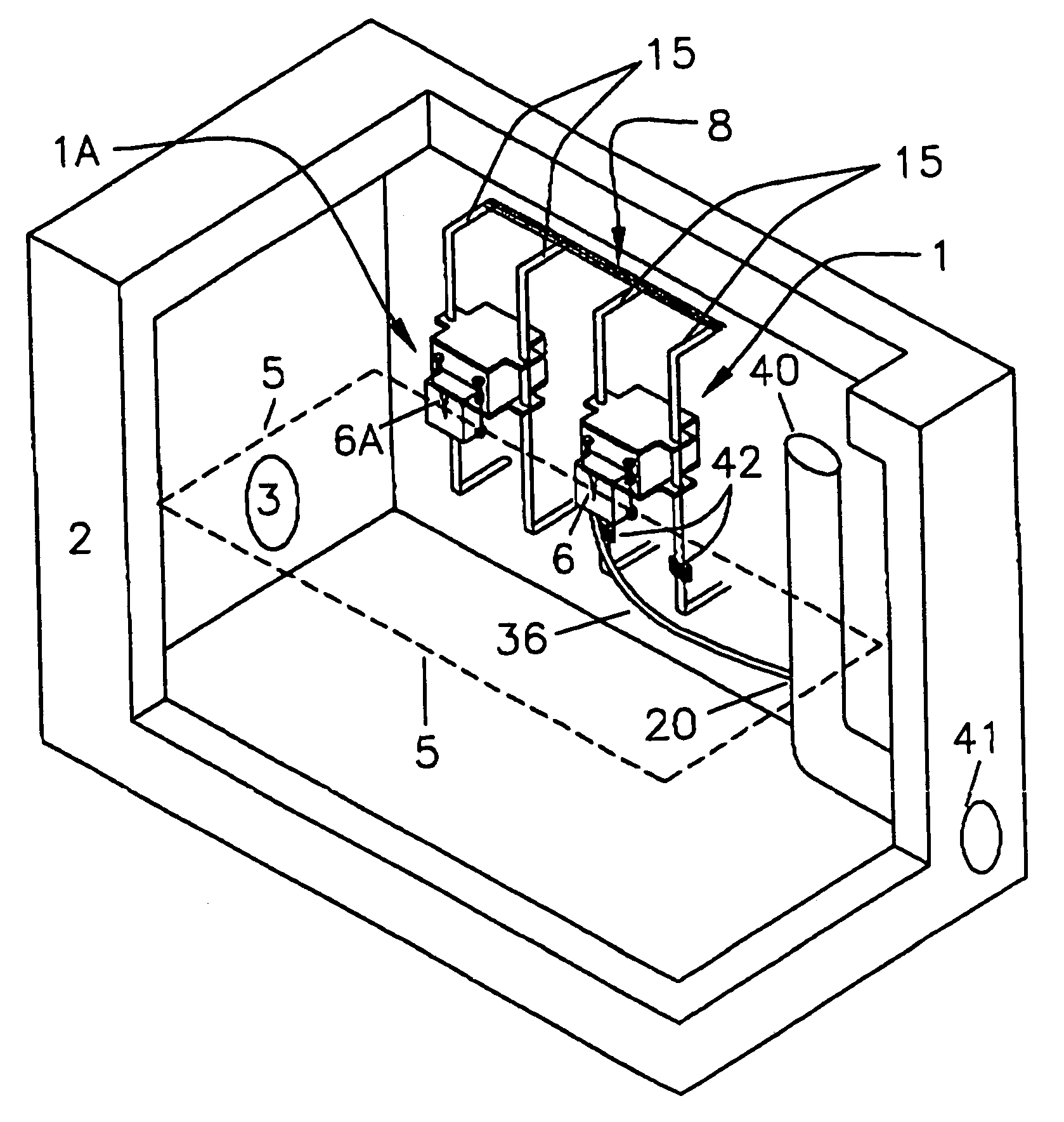
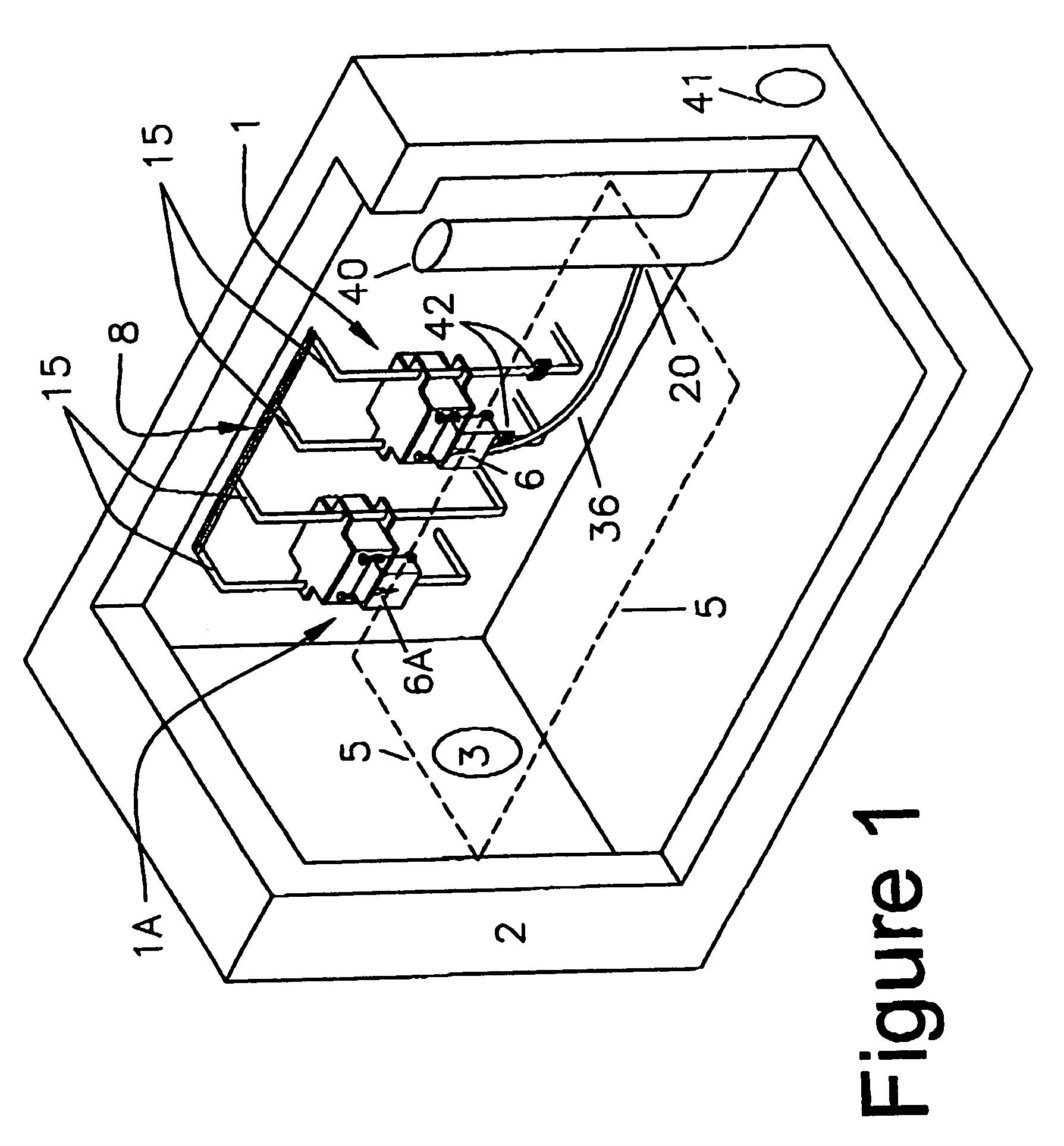
[0029]FIG. 1 illustrates an embodiment of the invention. In FIG. 1, floating weir assemblies 1 and 1A are disposed in vessel 2. Vessel 2 is partially filled with a fluid having a surface indicated by line 5. Fluid enters vessel 2 through fluid entrance 3. Floating weir assemblies 1 and 1A are mounted on optional support rack assembly 8. Each floating weir assembly includes a weir opening (6 and 6A, respectively) through which fluid enters the fluid inlet for removal from the vessel. The height of weir openings 6 and 6A are adjusted such that at least a portion of each of them is submerged below surface 5. Fluid entering weir opening 6 drains from vessel 2 by entering fluid inlet 17 (FIG. 2) and draining out of exit opening 50 into hose 36 through joint 20 into drainpipe 40. Fluid entering drainpipe 40 is removed from vessel 2 through fluid outlet 41.

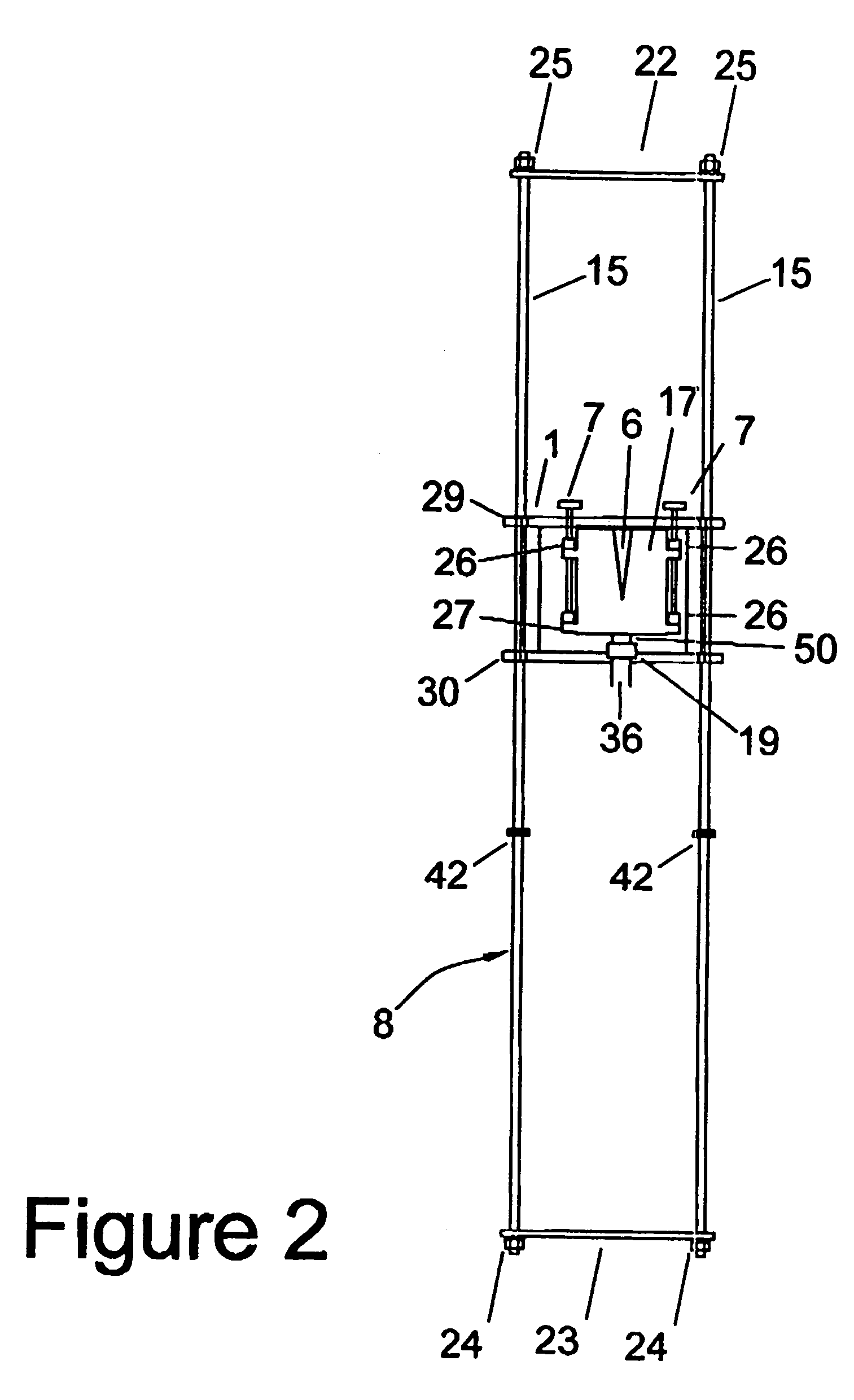
[0030]Turning to FIGS. 2 and 3, floating weir assembly 1 is seen to include buoyancy means 11 and fluid inlet 17. Buoyancy means 11 is ...


PUM


Abstract

Passive control of fluid flow from a vessel is provided by a floating weir assembly. The assembly includes a float and a weir opening that is in fluid communication with an outlet from the vessel. The weir opening and the fluid path connecting the weir opening and the outlet are designed such that the rate of outflow is determined by the geometry and position of the weir opening. The weir opening is preferably vertically adjustable so that desired outflow rates can be specified.

Description

[0001]This application claims benefit to provisional application Ser. No. 60 / 494,451, Aug. 11, 2003.BACKGROUND OF THE INVENTION[0002]This invention relates to methods for controlling the rate of flow of a fluid from a vessel.[0003]There are many instances in which it is necessary to control the rate of flow of fluids from a vessel. Rain water detainment systems, for example, are commonly used to control the rate at which rain water drains from a developed property. The systems generally include a reservoir into which rain water is collected, and one or more drains through which water is discharged from the reservoir. Maximum permissible flow rates out of these systems are generally specified by local regulatory bodies, and are usually keyed to the amount of rainfall.[0004]Rainfall is often expressed in terms of how frequently particular amounts of rainfall would be expected at a particular location. A rainfall that occurs on average once every two years, for example, is referred to ...

Claims


Application Information

Patent Timeline
Patent Type & Authority Patents(United States)
IPC IPC(8): E02B7/20E03F5/10
CPCE03F5/101E03F5/107
Inventor FLEEGER, HOWARD W.
Owner FLEEGER HOWARD W
Why Eureka
Try Eureka