
Interlock assembly and safety switch employing the same

a safety switch and interlocking technology, applied in the direction of air-break switches, tumbler/rocker switches, switchgear with a retractable carriage, etc., can solve the problems of potential safety threats, known safety switches continue to suffer from a unique set, etc., and achieve the effect of eliminating improper operation of safety switches

Active Publication Date: 2006-02-14
EATON INTELLIGENT POWER LIMITED
View PDF13 Cites 18 Cited by
  • Summary
  • Abstract
  • Description
  • Claims
  • Application Information

AI Technical Summary

Benefits of technology

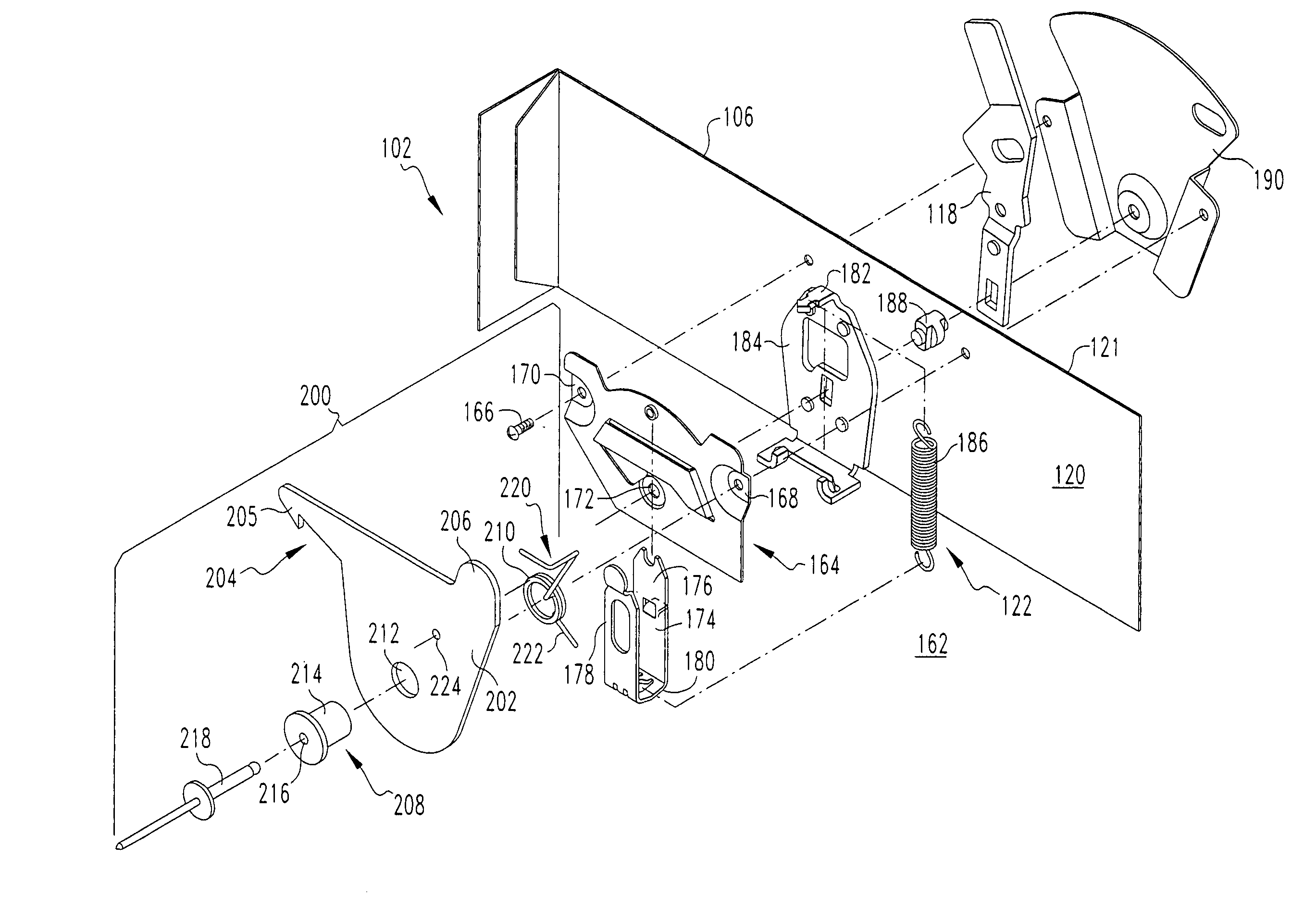
[0014]These needs and others are satisfied by the present invention, which is directed to an interlock assembly for safety switches. The interlock assembly functions to resist operation of the safety switch when the enclosure housing the electrical components of the switch is open. The switch may only be operated with an open door or with the cover removed, when the interlock is manually overridden or defeated. Thus, by substantially eliminating improper operation of safety switches (e.g., arbitrarily activating the switch while the cover is open) and known safety hazards associated therewith, the present invention provides a significant and valuable safety feature.
[0018]The side wall of the enclosure may have an edge and the sensing portion of the pivotal lever may be a projection structured to project beyond the edge in order that the cover of the enclosure engages and deflects it when the cover is closed, thereby overcoming the bias and causing the pivotal lever to pivot and unlock the arm of the spring-biased drive link.

Problems solved by technology

While the foregoing operating assembly, the spring-toggle mechanism therefor, and the snap action it affords represent significant achievements in the art, known safety switches continue to suffer from a unique set of disadvantages, one of which poses a potential safety threat.
This presents a potential safety issue, wherein an operator could be exposed to the arcing or sparking typically produced when energizing or opening a circuit.

Method used


Image

  • Interlock assembly and safety switch employing the same
  • Interlock assembly and safety switch employing the same
  • Interlock assembly and safety switch employing the same

Examples


Embodiment Construction

[0027]For purposes of illustration, the invention will be described as applied to an interlock for a general duty safety switch (e.g., 30–100 amp) housed within a covered enclosure, although it will become apparent that it could also be applied to other types of safety switches (e.g., without limitation, heavy duty safety switches and double throw safety switches) having an operating handle and an enclosure with a door or cover.

[0028]Directional phrases used herein, such as, for example, left, right, top, bottom, clockwise, counterclockwise and derivatives thereof, relate to the orientation of the elements shown in the drawings and are not limiting upon the claims unless expressly recited therein.

[0029]As employed herein, the term “fastener” refers to any suitable connecting or tightening mechanism expressly including, but not limited to, screws, bolts and the combinations of bolts and nuts (e.g., without limitation, lock nuts) and bolts, washers and nuts.

[0030]As employed herein, t...


PUM


Abstract

An interlock assembly is for locking the operating assembly of a safety switch when the cover thereof is open or removed. The safety switch includes an enclosure with the cover and side walls. The operating assembly includes a bracket and a spring-toggle mechanism with a spring-biased drive link having an arm. An operating handle, which is coupled to the spring-biased drive link, operates the operating assembly. The interlock assembly includes a pivotal lever having a catch and a sensing portion. A pivot receives a blind rivet and pivotally couples the pivotal lever to the side wall. A torsion spring biases the pivotal lever toward engaging the arm of the spring-biased drive link in order that the catch engages and locks the arm when the cover of the enclosure is open. The sensing portion is engaged and pivoted by the cover when it is closed.

Description

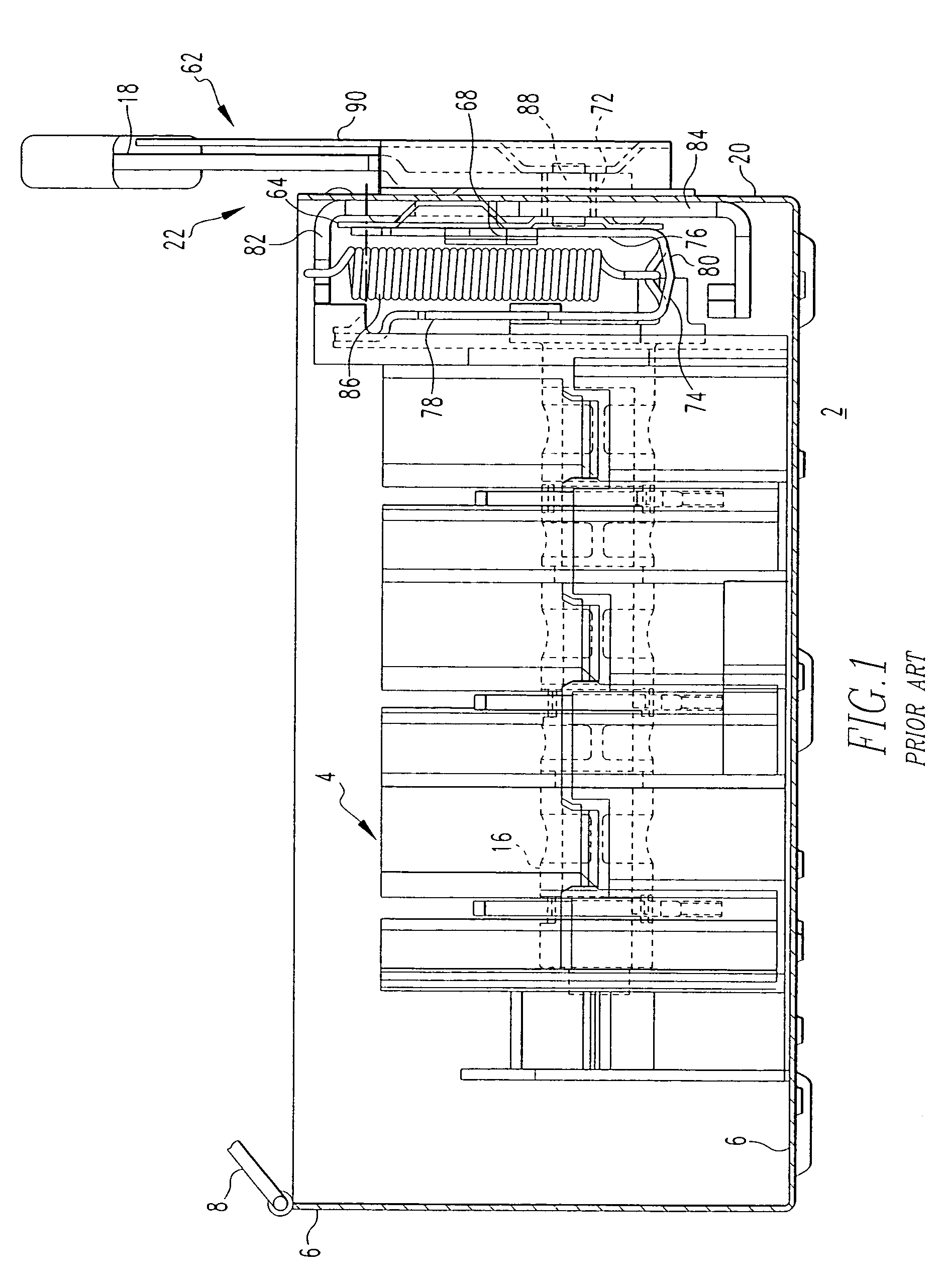
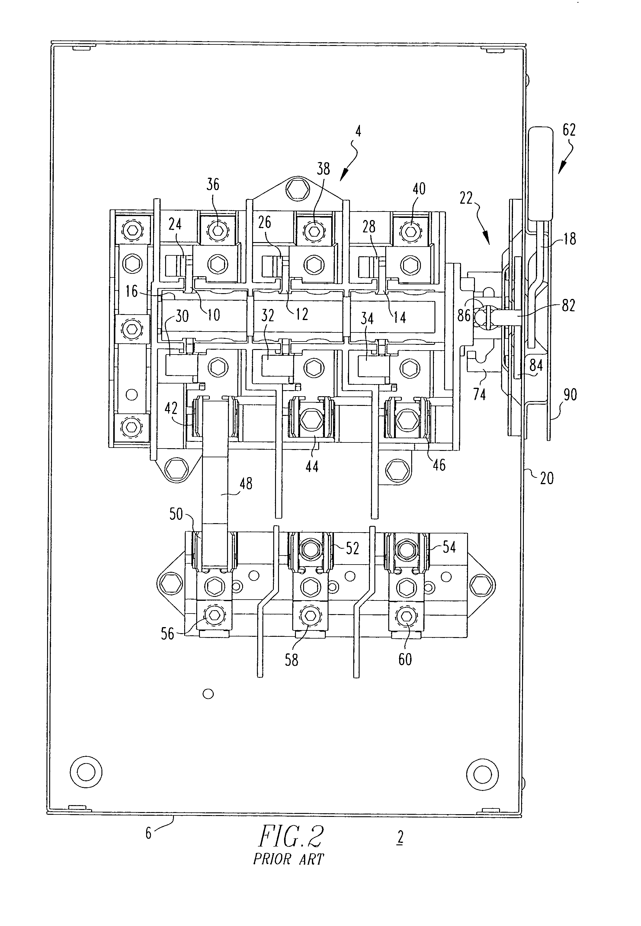
BACKGROUND OF THE INVENTION[0001]1. Field of the Invention[0002]The present invention relates generally to electrical switching apparatus and, more particularly, to an interlock assembly for safety switches. The invention also relates to safety switches employing an interlock assembly.[0003]2. Background Information[0004]Safety switches are used in electric power distribution systems in order to isolate a load or a portion of a power circuit.[0005]General duty safety switches are used, for example, in applications where electrical current ranges from about 30 amperes through about 100 amperes.[0006]For instance, general duty safety switches are commonly employed in residential and commercial applications and are suitable, for example, without limitation, for light duty motor circuits and service entrance applications.[0007]FIGS. 1 and 2 show a representative general duty safety switch 2. As shown, the safety switch 2 generally includes a switch mechanism 4 housed within an enclosure...

Claims


Application Information

Patent Timeline
IPC IPC(8): H01H33/46H01H9/20
CPCH02B11/133H01H9/22
Inventor BENDER, DOUGLAS R.CARSON, EDDIE D.
Owner EATON INTELLIGENT POWER LIMITED
Learn More