Roll supporting slide cutter assembly incorporating a traversable cutter tab and in particular capable of being supported within a carton enclosure associated with a wrap material roll

a slide cutter and assembly technology, applied in the direction of thin material handling, metal-working equipment, metal-working equipment, etc., can solve the problems of unwound packaging not being properly broken, bunched or folded together, and substantially rendered useless sectioned packaging, so as to prevent inadvertent removal and maximize the width of the wrap

Inactive Publication Date: 2006-02-21
REYNOLDS FOIL
View PDF70 Cites 39 Cited by
  • Summary
  • Abstract
  • Description
  • Claims
  • Application Information

AI Technical Summary

Benefits of technology

[0014]An axially extending and interior channel is associated with the rail and within which is seated the track seating portion of the cutter assembly. End stops are further associated with the upper edge of the main body and, upon assembly of the rail, prevent inadvertent removal of the cutter tab from the rail. End stop geometry works in conjunction with the cutting tab design to maximize the width of the wrap that can be sectioned for a given slide cutter assembly width and by virtue of permitting the cutting tab to extend partially beyond the associated rail.

Problems solved by technology

Shortcomings associated with the conventionally known knife-edged packaging include the incidence of the unwound packaging not severing properly and / or becoming bunched or folded together.
With particular regards again to such conventional types of packaging, this can result in the sectioned packaging being substantially rendered useless.

Method used


Image

  • Roll supporting slide cutter assembly incorporating a traversable cutter tab and in particular capable of being supported within a carton enclosure associated with a wrap material roll
  • Roll supporting slide cutter assembly incorporating a traversable cutter tab and in particular capable of being supported within a carton enclosure associated with a wrap material roll
  • Roll supporting slide cutter assembly incorporating a traversable cutter tab and in particular capable of being supported within a carton enclosure associated with a wrap material roll

Examples


Embodiment Construction

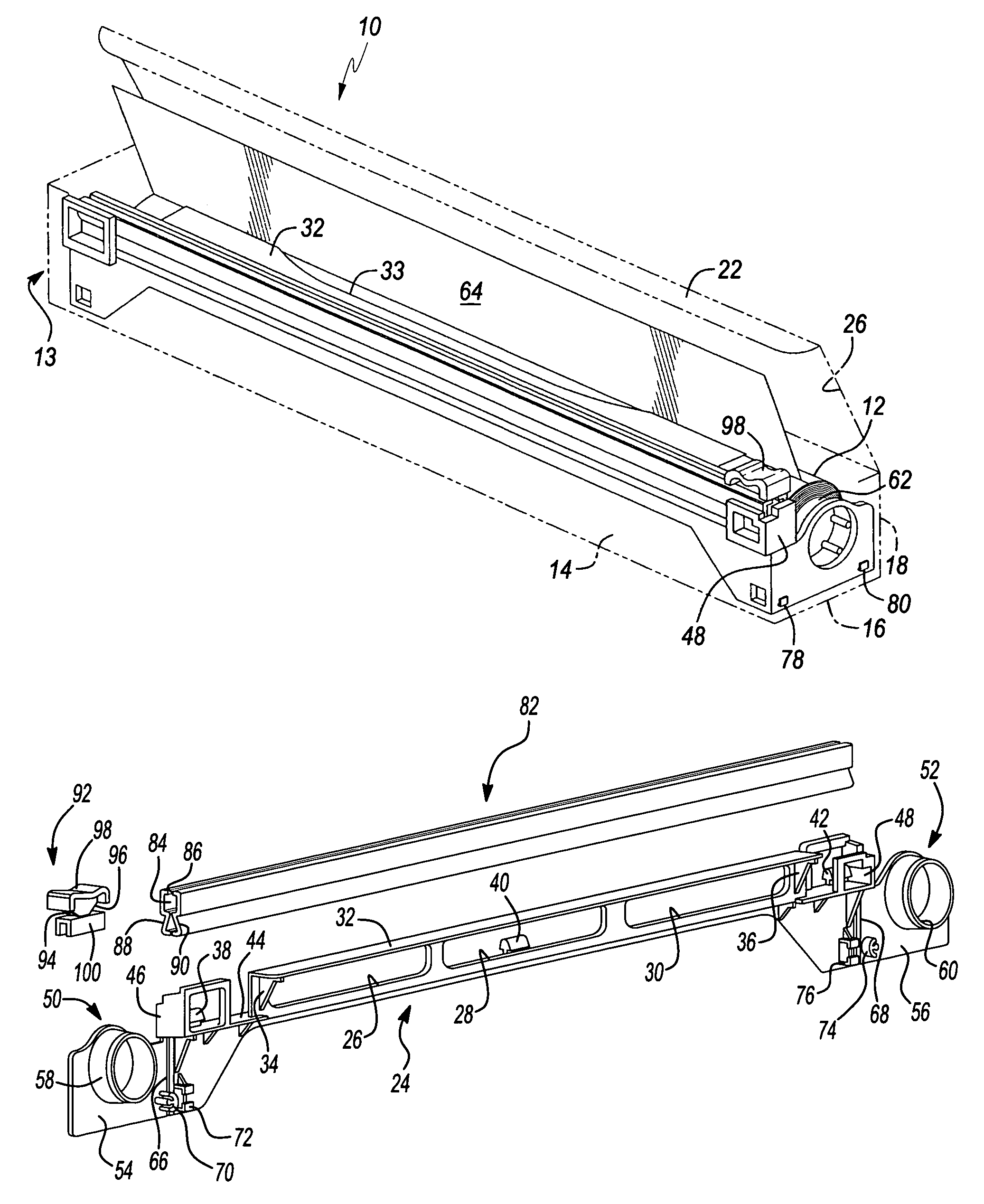
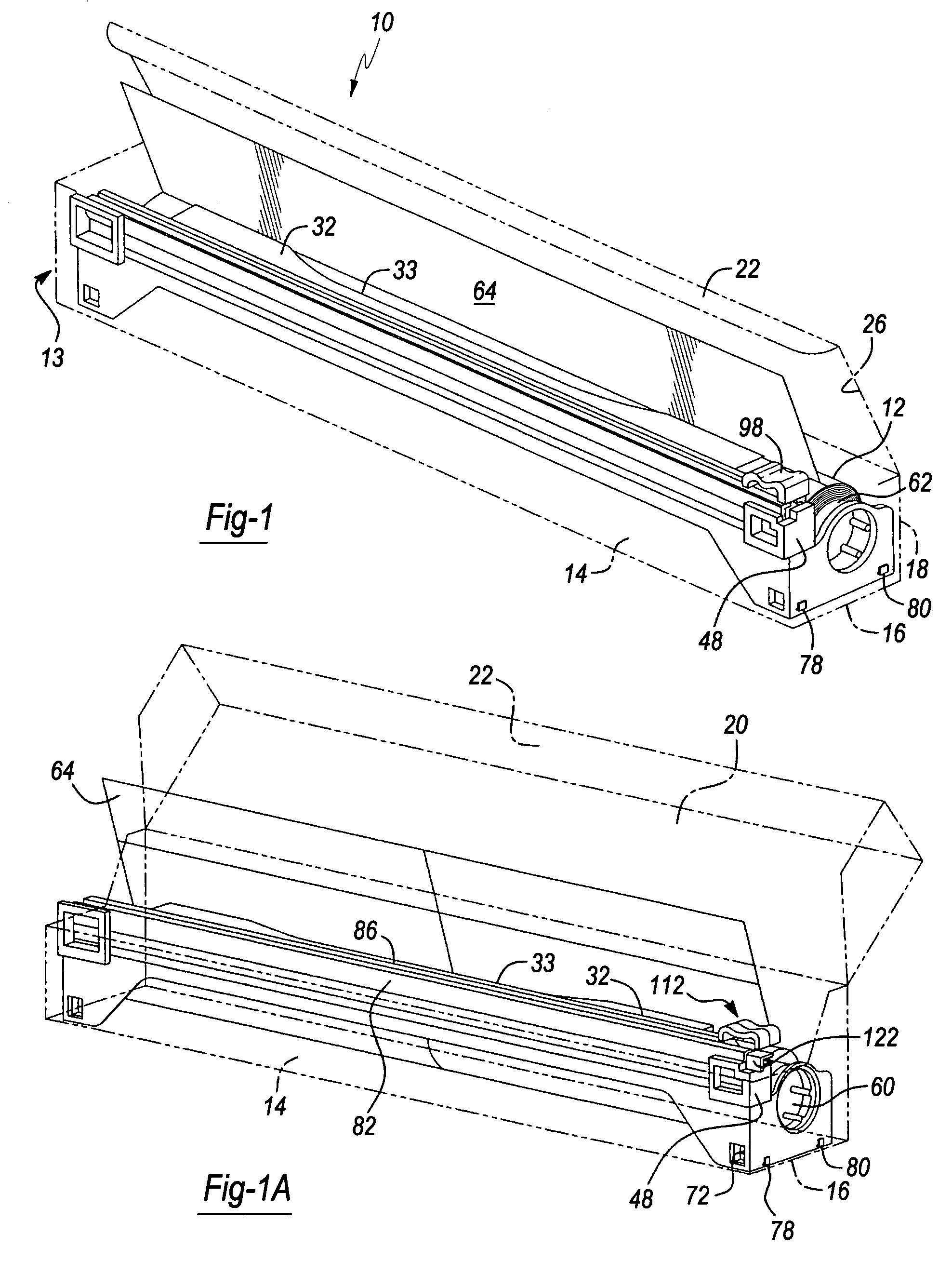
[0031]Referring to FIG. 1, a slide cutter assembly is illustrated at 10 for use in rotatably supporting and sectioning lengths of packaging material associated with a wound roll 12 of such material. As described previously, the present invention is an improvement over prior art devices in that it is capable of supporting the roll of packaging material in secure and rotatable fashion, either in an over dispensing or under dispensing condition, this further being a variable of the direction in which the leading edge of the roll unreels.

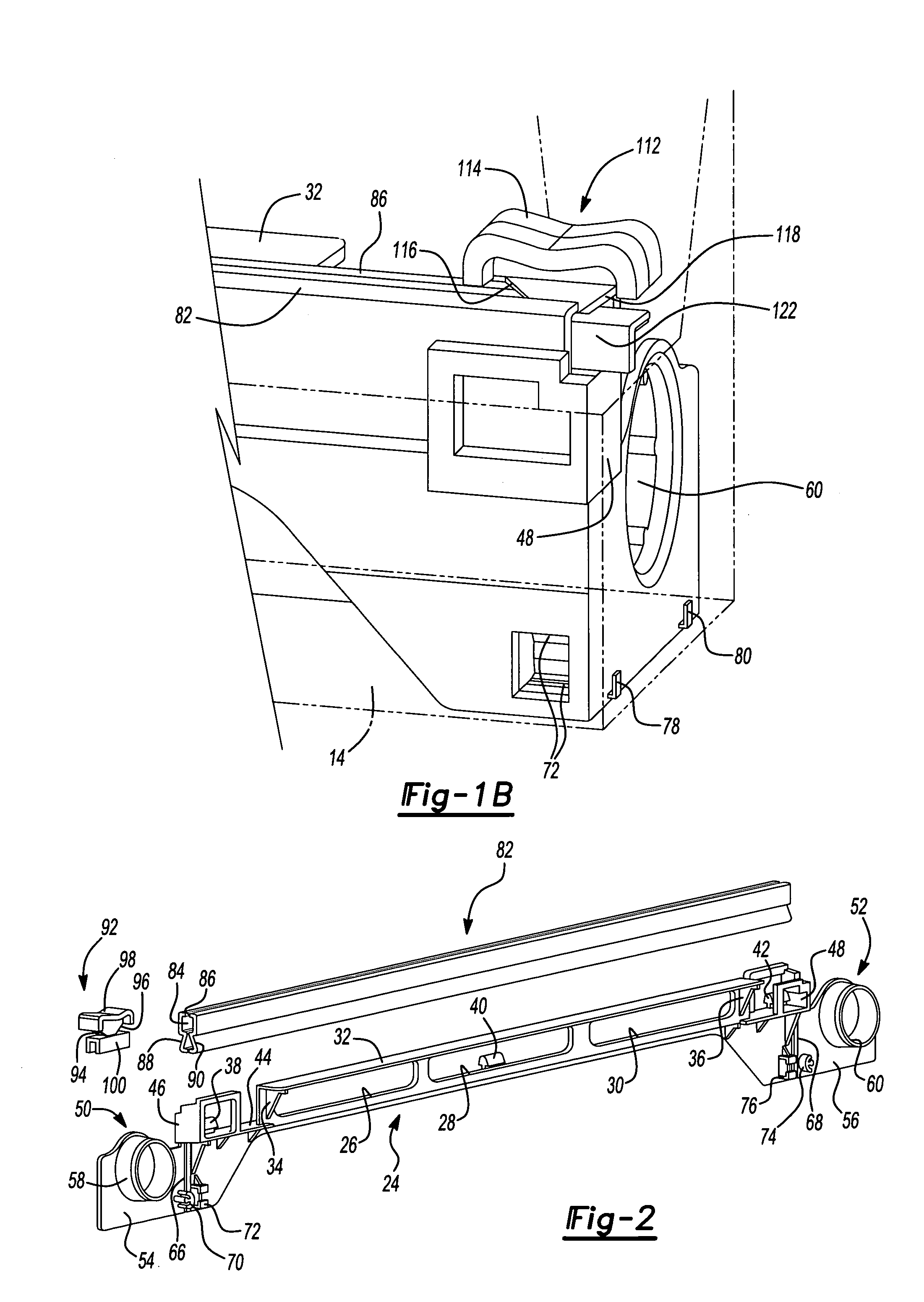
[0032]Additionally, the slide cutter assembly 10 is capable of functioning alone with the wound roll 12 of packaging material supported thereupon or, alternatively, may be inserted in substantially contained fashion within the generally elongated and three-dimensional configuration of the product packaging. The carton, 13, as shown in phantom at 13 in FIG. 1, includes three elongated and interconnecting sides 14, 16 and 18, a fourth side 20 hingedly con...


PUM

PropertyMeasurementUnit
angleaaaaaaaaaa
flexibleaaaaaaaaaa
distanceaaaaaaaaaa

Abstract

A slide cutter assembly for use in sectioning lengths of a packaging material drawn from a roll. The device includes an elongated and shaped body. A first roll supporting portion is located at a first end of said body and a second roll supporting portion is likewise located at a second end of the body. A cutter assembly extends from a selected lengthwise extending edge of the body and upon which an unwound length of the packaging material comes into contact. The cutter assembly incorporates a traversable blade for sectioning from the roll the length of packaging material. The roll of packaging typically comes in a generally elongated and three-dimensional shaped packaging, the cutter device being constructed so that it may be supported within an interior defined by the packaging and upon first mounting the roll between the first and second roll supporting portions.

Description

CROSS-REFERENCE TO RELATED APPLICATIONS[0001]The present application claims the priority of U.S. Provisional Application Ser. No. 60 / 388,038, filed Jun. 12, 2002, and entitled “Insertable Slide Cutter for Use with Wrap and Packaging Materials”; as well as the priority of U.S. Provisional Application Ser. No. 60 / 397,961, filed Jul. 23, 2002, and entitled “Slide Cutter Assembly Incorporated Into a Container Configuration Which Holds and Dispenses a Roll of Packaging Materials”; as well as the priority of U.S. Provisional Application Ser. No. 60 / 401,683, filed Aug. 6, 2002, and entitled “Slide Cutter Assembly for Use With a Roll of Packaging Materials”; as well as the priority of U.S. Provisional Application Ser. No. 60 / 414,159, filed Sep. 27, 2002, and entitled “Slide Cutter Insert Assembly with Configured Cutter Tab”; as well as the priority of U.S. Provisional Application Ser. No. 60 / 423,543, filed Nov. 4, 2002, and entitled “Slide Cutter Insert Assembly Including Gripping Tabs for ...

Claims


Application Information

Patent Timeline
Patent Type & Authority Patents(United States)
IPC IPC(8): B26D1/04B65H75/32B26D1/06B26D1/10B65H16/06B65H35/00
CPCB26D1/045B26D1/065B26D1/105B65H16/005B65H35/002B65H35/0086B65H16/06Y10S83/949B65H2301/5154Y10T83/8822Y10T225/247Y10T83/7507Y10T83/8769Y10T83/896
Inventor NICHOLS, MONICA STAUTNERGRASSEL, WILLIAM H.POWELL, G. DOUGLASRIDER, RICHARD W.SHOUP, JEFFREY M.SKILES, JEAN ANNSPEER, ROBERT J.MICLE, FRANK R.PLANK, DAVID
Owner REYNOLDS FOIL
Why Eureka
Try Eureka