Clutch brake

a technology of clutch brake and release bearing, which is applied in the direction of brake system, gearing, transportation and packaging, etc., can solve the problems of inability to maintain the disengaged position of the release bearing, and the traditional clutch brake that operates by engagement with the release bearing is not compatible with a “wear-through” style master clutch

Active Publication Date: 2006-02-21
EATON CORP
View PDF11 Cites 34 Cited by
  • Summary
  • Abstract
  • Description
  • Claims
  • Application Information

AI Technical Summary

Problems solved by technology

In a “wear-through” style master clutch, the disengaged position of the release bearing is not consistently maintained over the life of the frictional components of the master clutch.
Therefore, traditional clutch brakes that operate by engagement with a release bearing are not compatible with a “wear-through” style master clutch.

Method used


Image

  • Clutch brake
  • Clutch brake
  • Clutch brake

Examples


Embodiment Construction

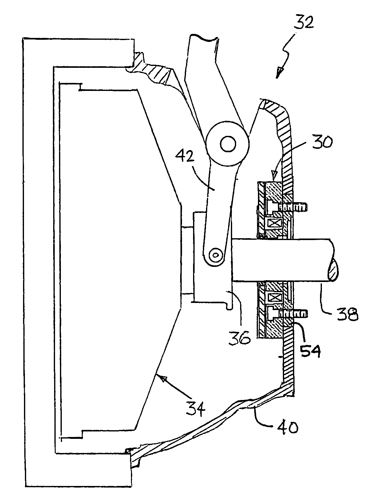
[0043]Referring now to the drawings, various embodiments of the present invention are described in detail. Certain terminology will be used in the following description for convenience in reference only and will not be limiting. For example, the terms “transmission” and “master clutch” as used herein shall include all types of gear change transmissions, including single countershaft and twin countershaft types and all types of driveline master clutches, respectively. Further, while the braking apparatus of the present invention may be used in various applications requiring the rotational slowing of a shaft, the present invention is particularly suited for use as a clutch brake for slowing rotation of a transmission input shaft disposed between a driveline master clutch and a transmission of a motor vehicle, and will be described in connection therewith.

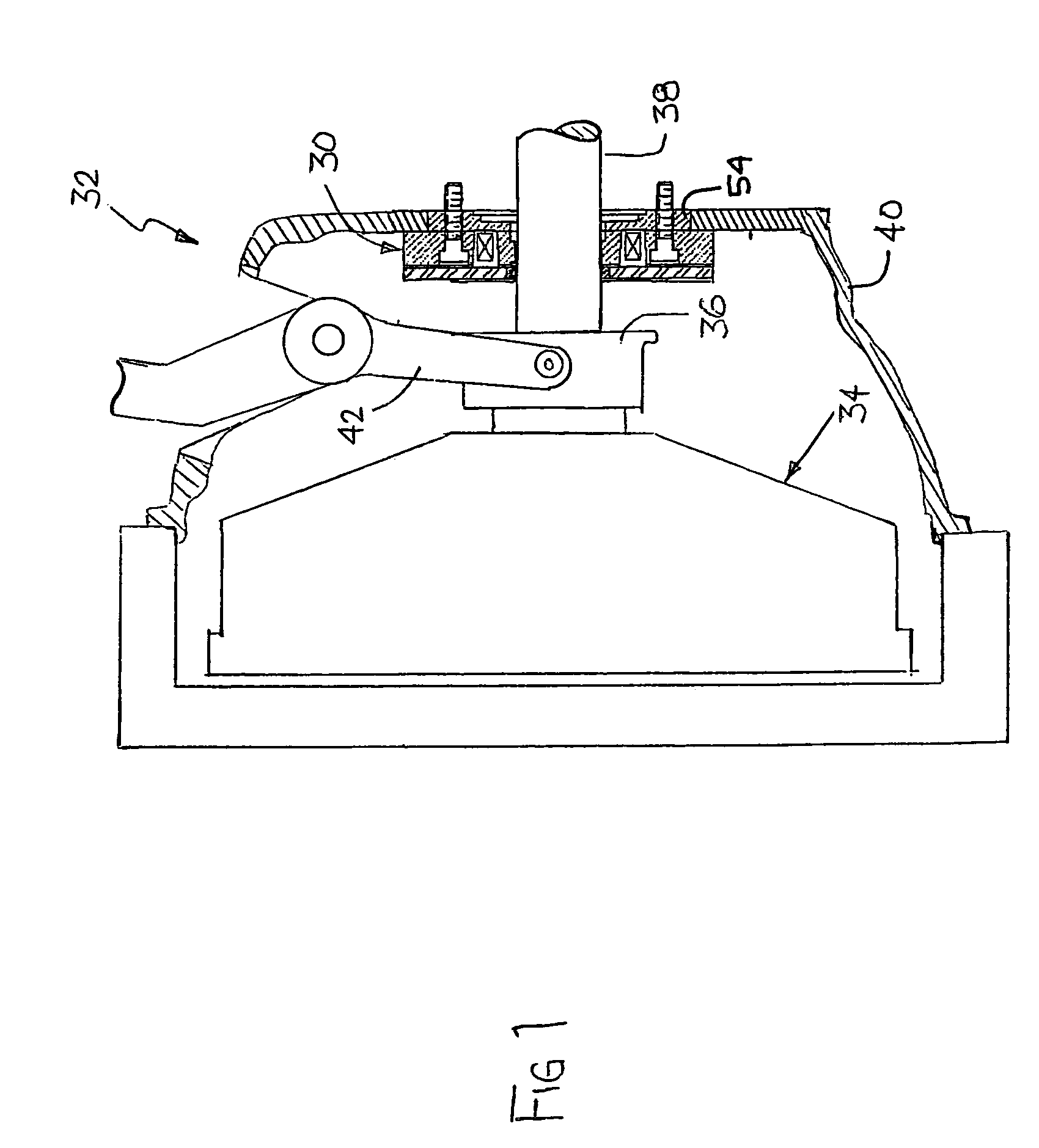
[0044]Referring to FIG. 1 of the drawings, a side elevation view of a clutch brake 30 of the present invention is shown installed in...


PUM


Abstract

A clutch brake is provided that includes a brake housing adapted to be non-movably secured relative to a driveline master clutch. The brake housing includes a through-hole sized to allow passage of a shaft and at least one source of magnetic flux. The clutch brake also includes an armature secured for rotation with the shaft and positioned axially adjacent the brake housing in a disengaged state. At least a portion of the armature is adapted to move axially on the shaft in the presence of magnetic flux to contact the brake housing in an engaged state and inhibit rotation of the armature and the shaft.

Description

BACKGROUND OF THE INVENTION[0001]1. Field of the Invention[0002]The present invention relates to heavy-duty driveline master clutches of the type used in large vehicles such as trucks, tractor-trailers or the like and, more particularly, to a clutch brake for use with a driveline master clutch.[0003]2. Description of the Related Art[0004]The use and function of a clutch brake is well known in the art of vehicle driveline systems. A clutch brake is a device used to rapidly slow the rotational speed of a transmission input shaft when a driveline master clutch is disengaged to facilitate the shifting of gears in the transmission. Without a clutch brake, the time required to shift a transmission would be significantly increased, thereby complicating operation of the transmission in various driving modes.[0005]A conventional clutch brake is a disc-shaped device, a portion of which is splined to the input shaft of the transmission and is activated by a master clutch release mechanism when...

Claims


Application Information

Patent Timeline
Patent Type & Authority Patents(United States)
IPC IPC(8): F16D67/02B60T1/06F16D65/14F16D67/06F16H3/12F16H61/04
CPCF16D67/02F16D67/06F16H2003/123F16D2123/00F16D2121/20
Inventor HORNBROOK, MICHAEL J.MCCUTCHEON, STEVEN E.
Owner EATON CORP
Why Eureka
Try Eureka