Liquid image formation apparatus and liquid developing device

a technology of liquid image and developing device, which is applied in the direction of electrographic process apparatus, instruments, optics, etc., can solve the problems of image fog caused by excess toner, and excess toner may not be fully removed

Inactive Publication Date: 2006-02-21
RICOH KK
View PDF59 Cites 14 Cited by
  • Summary
  • Abstract
  • Description
  • Claims
  • Application Information

AI Technical Summary

Benefits of technology

[0021]It is an object of this invention to provide a liquid image formation apparatus capable of preventing a transfer medium and peripheral members from being soiled due to residual excess toner by removing the excess toner on a latent image carrier as much as possible.
[0022]Another object of this invention is to provide a liquid developing device capable of enhancing reliability and durability of a developing roller by eliminating permanent distortion of the developing roller due to being in a pressure and contact state.
[0023]A further object of this invention is to provide a liquid developing device and an image formation apparatus capable of forming high quality images by preventing image fog and of reducing a carrier liquid.
[0027]A cleaning member in contact with the surface of a removing member is used here as a cleaning unit. If the width in a main scanning direction of the removing member is wider than the width in the main scanning direction of the cleaning member, as shown in FIG. 5, the removed excess toner is brought to both ends of the cleaning member and re-adheres in a streak to the surface of the removing member. The streaked toner is pressed and spread at the contact part between the removing member and the latent image carrier to remain between the removing member and the latent image carrier. This may bring about lowering of a function of the removing member that removes the excess toner from the surface of the latent image carrier.
[0029]According to this invention, permanent distortion of the developing roller due to being in a pressure and contact state is eliminated to enable enhancement in reliability and durability of the developing roller.
[0032]According to this invention, a time required until the contact part of the photoreceptor with the developing roller reaches the sweep roller is set to 0.5 sec or below, thus obtaining excellent developing characteristics with less image degradation.

Problems solved by technology

Thus, image fog may occur due to the excess toner.
However, in a structure in which a removing member for removing excess toner from the latent image carrier is provided, if an area where the toner is removed by the removing member is smaller relative to an area where the liquid developer is applied to the latent image carrier, the excess toner may not fully be removed.
Image fog due to the excess toner is found more noticeable particularly when a highly viscous and highly concentrated liquid developer is used.
Therefore, if the developing roller is in contact with the photoreceptor and left standing as it is for long time, distortion may occur in the developing roller.
Further, the surface of the photoreceptor in contact with the developing roller may be soiled.
However, if the photoreceptor and the developing roller are brought into contact with or separated from each other, the surface of the developing roller and the surface of the photoreceptor may be damaged or scratched due to a difference between a rotating speed of the photoreceptor and that of the developing roller.
Abnormal discharge may occur immediately before the developing roller comes into contact with the photoreceptor or immediately after the developing roller separates from the photoreceptor due to a potential difference between the surface of the developing roller and that of the photoreceptor, thereby the surface of the developing roller or the surface of the photoreceptor may be damaged.
Further, the toner adheres to the photoreceptor, which causes the toner consumption to increase.
In this case, image fog due to this excess toner may occur.
Further, the carrier liquid adhering to the image portion and non-image portion may be unnecessarily consumed.

Method used


Image

  • Liquid image formation apparatus and liquid developing device
  • Liquid image formation apparatus and liquid developing device
  • Liquid image formation apparatus and liquid developing device

Examples


first embodiment

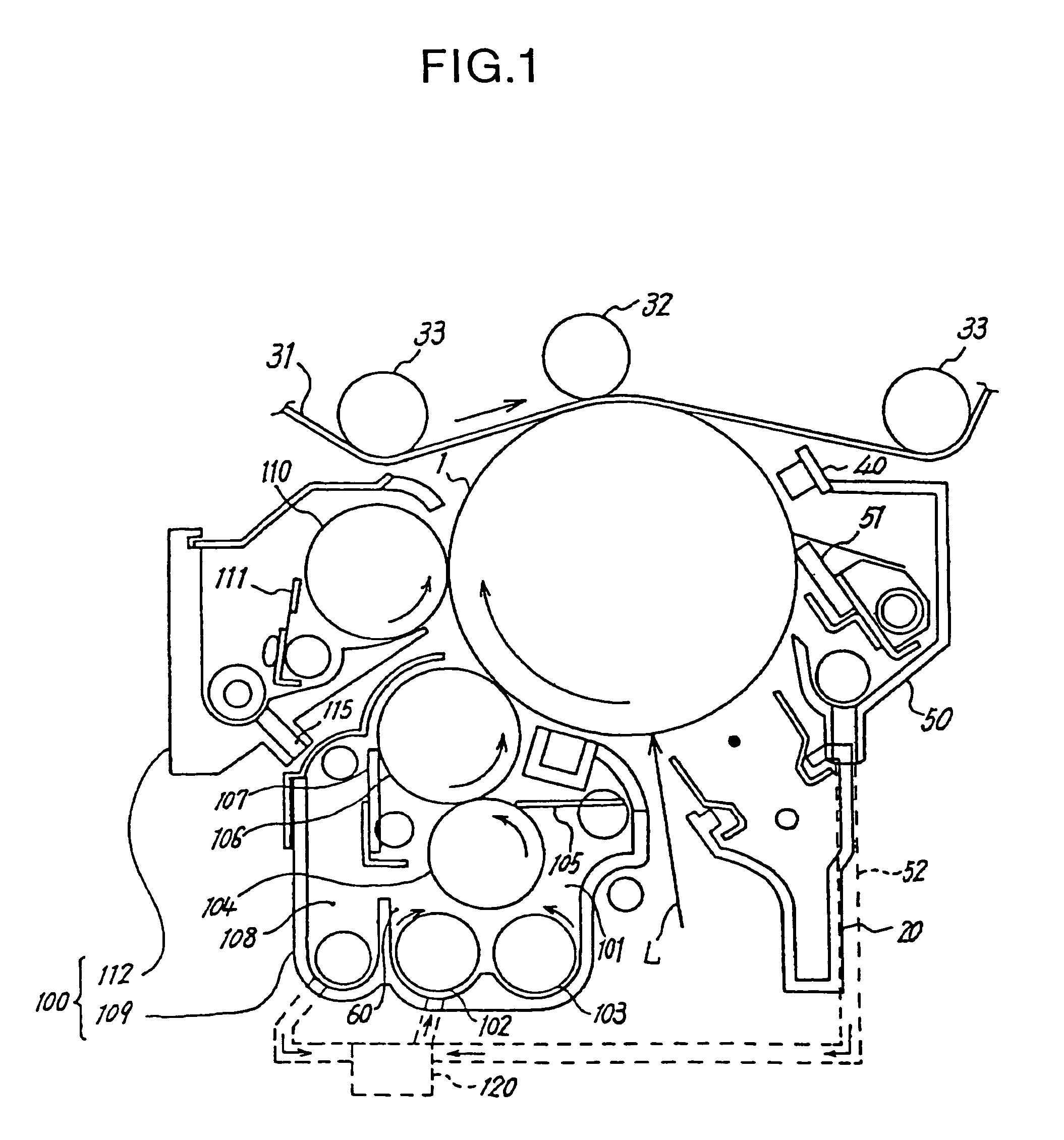
[0076]FIG. 1 schematically shows the key section of a printer according to a In this figure, the printer comprises the charger 20, exposing device, not shown, that irradiates exposure light L to the photoreceptor drum 1, wet-type developing device 100, transfer device composed of the intermediate transfer belt 31 and transfer roller 32, discharge lamp 40, and the drum cleaning device 50, each of which is disposed around the photoreceptor drum 1 as a latent image carrier.

[0077]The surface of the photoreceptor drum 1 is formed of amorphous silicon (a-Si), and is driven to rotate in the direction of the arrow in the figure by a driving unit, not shown, during printing. The photoreceptor drum 1 whose surface is formed of the amorphous silicon (a-Si) exhibits more excellent mechanical strength than that of an organic photoconductor (OPC), prolongs its life, and enhances the level of safety.

[0078]The charger 20 uniformly charges the surface of the photoreceptor drum 1 driven to rotate in...

second embodiment

[0126]FIG. 7 is a schematic diagram showing this invention in which the developing device according to this invention is applied to an electrophotographic copier as an example of the image formation apparatus.

[0127]In FIG. 7, the legend 201 represents the photoreceptor drum as a latent image carrier. There are the charger 202, developing roller 242, sweep roller 243, and the transfer device 205, which are successively disposed around the photoreceptor drum 201 in its rotating direction. The cleaning device 206 is disposed between the transfer device 205 and the charger 202, and the exposing device 203 is disposed between the charger 202 and the developing roller 242.

[0128]The developing roller 242 is brought into contact with the photoreceptor drum 201 with a predetermined pressure during use, and a prescribed nip width is formed between the photoreceptor drum 201 and the developing roller 242.

[0129]Although amorphous silicon is used here as a material of the photoreceptor drum 201,...

third embodiment

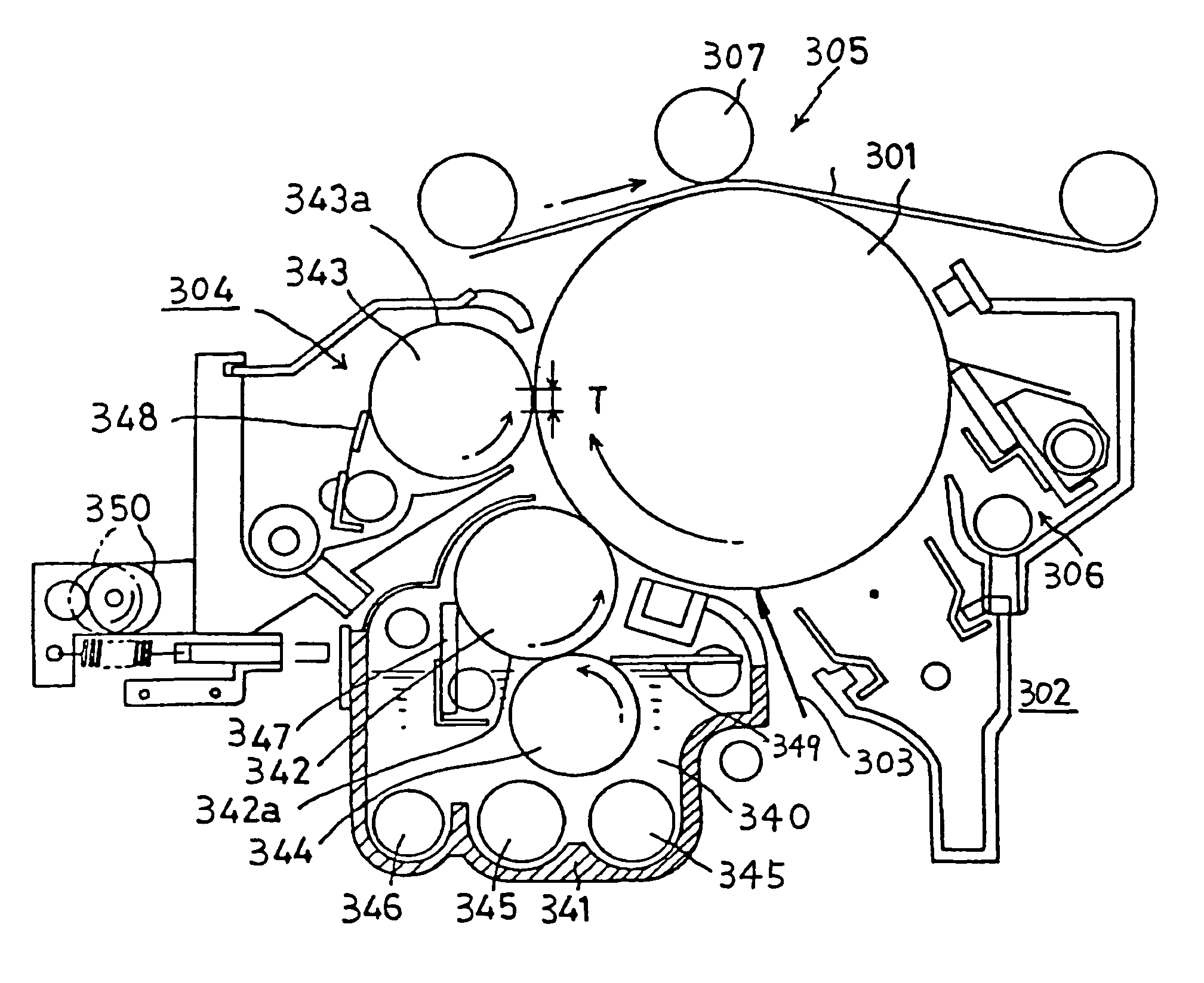
[0172]The developer 340 used in the image formation apparatus of the third embodiment is not the liquid developer of low viscosity (about 1 cSt) and low concentration (about 1%) based on conventionally available Isopar (trademark of Exxon) as a carrier, but is a highly viscous and highly concentrated liquid developer. The developer 340 to be used is any developer having a viscosity within a range from 50 cSt to 5000 cSt and a concentration within a range from 5% to 40%. The carrier liquid to be used is any of highly insulating liquid carriers such as silicone oil, normal paraffin, Isopar M (trademark: Exxon), vegetable oil, or mineral oil. It is possible to select volatility or non-volatility for any purpose. The toner particles range in size from submicrons to about 6 μm, and any particle size can be selected in accordance with each purpose.

[0173]The developing device 304 as characteristics of the third embodiment will be explained below. As shown in FIG. 12, the developing device ...


PUM


Abstract

An excess toner removal area is made broader over the whole area with respect to a developer applied area that is broader than an image effective area. Thereby a liquid developer, that tends to spread slightly broader than the applied area after being applied to a photoreceptor drum, is removed by a sweep roller that can sweep excess toner present in an area broader than the original applied area and an excess toner remaining area is then prevented from being formed on the photoreceptor drum. Accordingly, the excess toner on the latent image carrier is removed as much as possible, and a transfer medium and peripheral members are prevented from being soiled due to residual excess toner.

Description

[0001]This application is a Division of Application Ser. No. 10 / 617,769 filed on Jul. 14, 2003 now U.S. Pat. No. 6,829,460 which is DIV of 10 / 050,959 filed Jan. 22, 2002 which is now U.S. Pat. No. 6,640,073.FIELD OF THE INVENTION[0002]The present invention relates to a liquid image formation apparatus and a liquid developing device used for electrophotographic wet-type copiers, printers, or facsimiles.BACKGROUND OF THE INVENTION[0003]Conventionally, there have been known various types of liquid image forming devices that perform development using a liquid developer consisting of a carrier liquid and toner dispersed therein (see e.g., Japanese Patent Application Laid-Open No. 7-209922, Japanese Patent Application Laid-Open No. 7-152254, or Japanese Patent Application Laid-Open No. 7-21935). Further, the applicant of this invention has proposed an image forming method in Japanese Patent Application No. 11-38447, in which a developer carrier having an elastic layer is brought into cont...

Claims


Application Information

Patent Timeline
Patent Type & Authority Patents(United States)
IPC IPC(8): G03G15/10G03G15/11
CPCG03G15/11
Inventor KUROTORI, TSUNEOSASAKI, TSUTOMUYOSHINO, MIETAKEUCHI, NORIYASUNAKANO, TOHRUTAKEDA, YUSUKE
Owner RICOH KK
Why Eureka
Try Eureka