Cushioning element

a technology of cushioning elements and cushioning rings, which is applied in the field of cushioning rings, can solve the problems of easily fatigued hand and finger of users, prone to rebounding to initial shapes,

Inactive Publication Date: 2006-02-28
FERRARA DANIEL A
View PDF74 Cites 62 Cited by
  • Summary
  • Abstract
  • Description
  • Claims
  • Application Information

AI Technical Summary

Benefits of technology

[0009]The deformable portion of the encasing member can be made of a material capable of deforming in response to a deforming force applied thereto. Preferably, the deformable portion is made of a pliable material so that it can yield to the deforming force along with the flowable particulate matter. As a result, the deformable portion may, along with the flowable particulate matter, provide a cushioning effect, such as a comfortable grip or shock absorption. The area, size, and thickness of the deformable portion can be determined according to the specific application of the cushioning element.
[0010]The cushioning element of the present invention is intended to be used (among other things) with an article to provide a cushioning effect upon gripping the cushioning element on the article, or to provide a cushioning effect upon contact with another article, or to provide a cushioning effect upon contact with a part of a human body. One application of the cushioning element is to provide a comfortable grip for hand-held articles, such as writing instruments, razors, toothbrushes, utensils, and tools. The cushioning element can also provide a comfortable cushioning for such articles as splints or seatings. In addition, the cushioning element can provide shock absorption for articles which transmit impact to the user, such as impact tools (e.g., hammers), various sports equipments (e.g., helmets, knee pads, and rackets), and motor-driven devices (e.g., power drills or motorcycles). For each application, the cushioning element is constructed accordingly to fit onto a given article to provide an appropriate cushioning effect during use of the article.

Problems solved by technology

However, due to the nature of such grip elements, they tend to rebound to their initial shapes once the compressing force is released.
The continuous and tight holding of the grip element can easily fatigue the user's hand and fingers.

Method used


Image

  • Cushioning element
  • Cushioning element
  • Cushioning element

Examples


Embodiment Construction

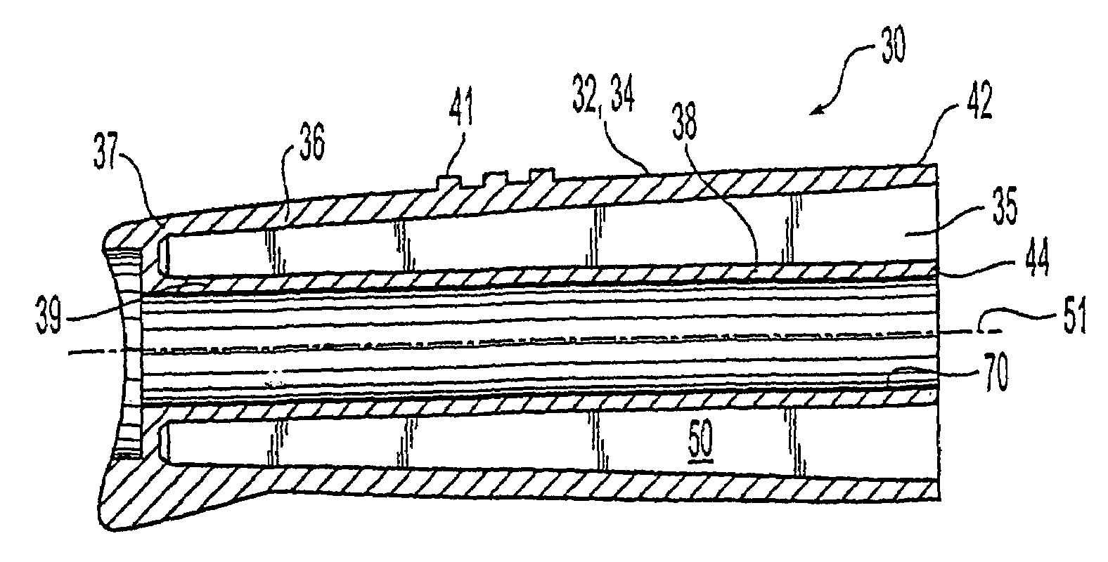
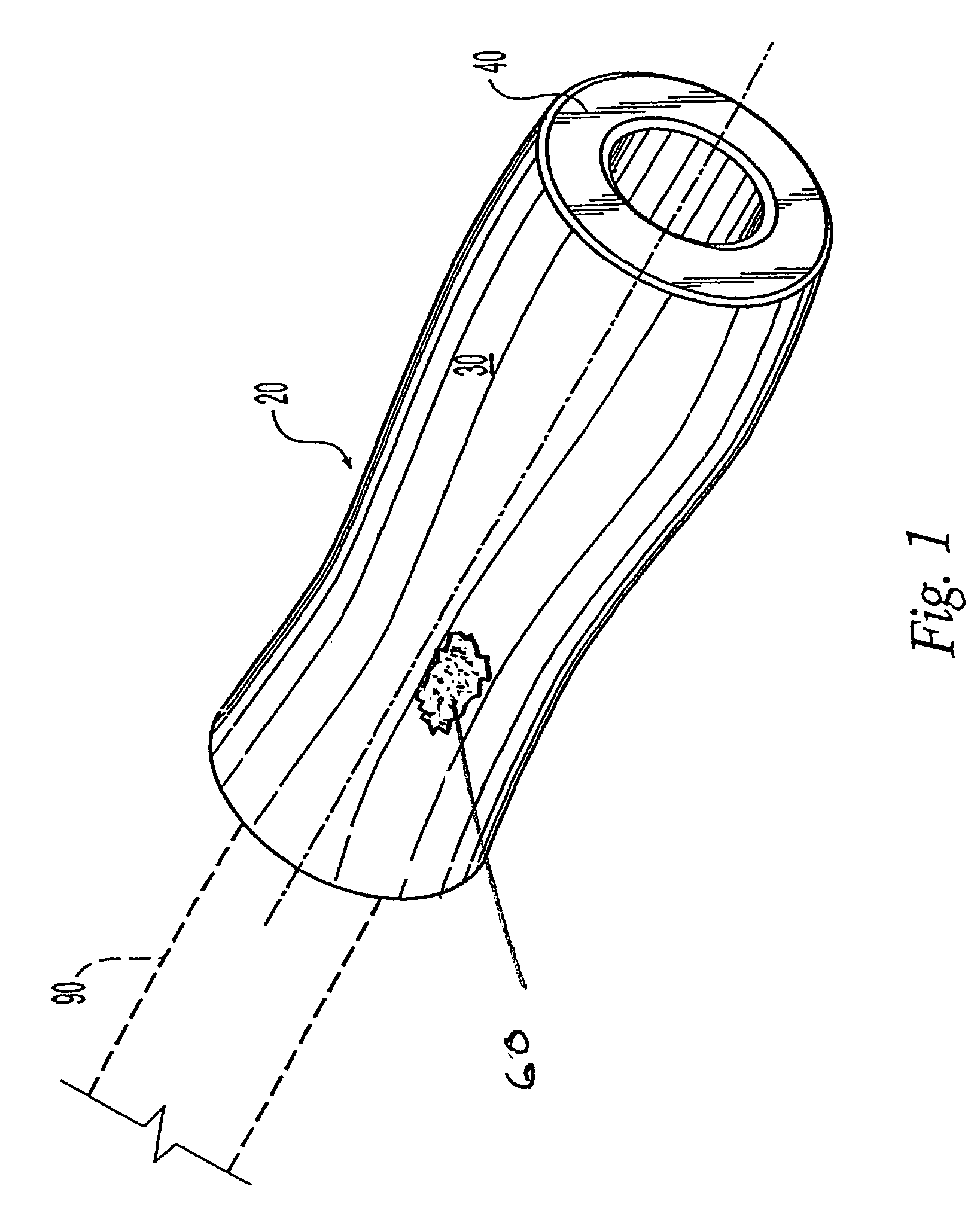
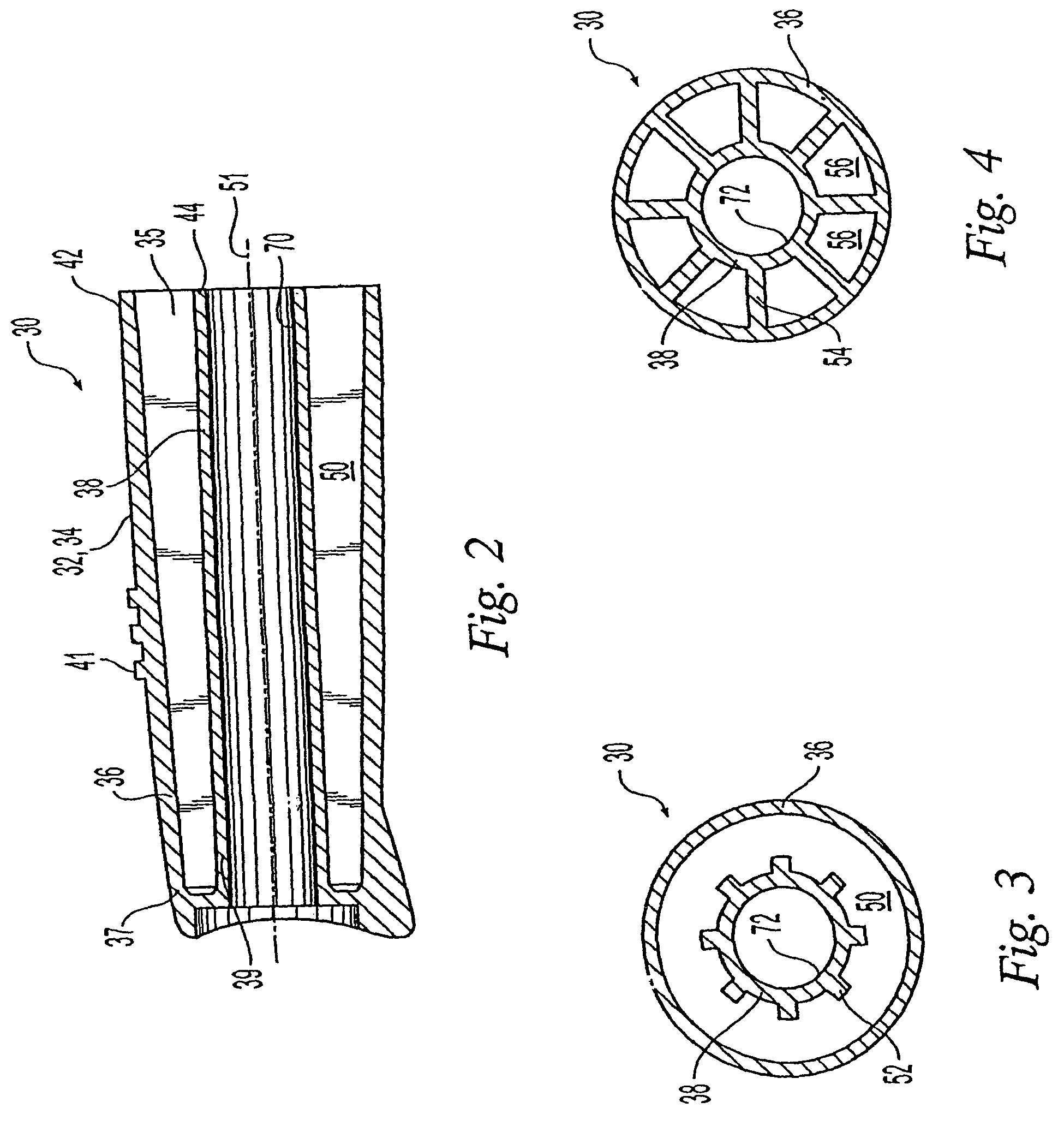
[0028]Exemplary cushioning elements embodying the principles of the present invention are shown throughout the drawings. In the following description of various embodiments of cushioning elements, similar elements or components thereof are designated with reference numbers that have the same last two digits and redundant description is omitted.

[0029]The cushioning elements of the present invention utilize flowable particulate matter to provide a cushioning effect upon application of a deforming force thereto. The particulate matter is capable of flowing within a filling chamber after being subjected to a deforming force. Additionally or alternatively, the particulate matter is capable of retaining the deformed shape even after the deforming force has been released.

[0030]The encasing member includes a deformable portion. Deformation of the deformable portion transmits the deforming force to the particulate matter and causes the same to flow and to conform to the-desired configuration...


PUM


Abstract

The present invention relates to a cushioning element adapted to be mounted on an article to provide cushioning therefor. The cushioning clement of the present invention has a bladder body at least partially defining a filling chamber. The filling chamber is filled with a flowable particulate matter. The present invention further includes a mounting member adapted to mount the bladder body onto the article. According to the present invention, at least a portion of the bladder body is deformable and the particulate matter within the filling chamber is capable of flowing inside the filling chamber upon the application of a deforming force to the deformable portion of the bladder body.

Description

CROSS-REFERENCE TO RELATED APPLICATIONS[0001]This application is a Continuation-in-Part of U.S. patent application Ser. No. 09 / 793,590 filed on Feb. 27, 2001, now U.S. Pat. No. 6,648,535, the entire disclosure of which is incorporated herein by reference.FIELD OF THE INVENTION[0002]The present invention relates generally to a cushioning element that is adapted to be mounted onto an article to provide cushioning therefor. More particularly, the cushioning element of the present invention contains a flowable particulate filling material. The present invention further relates to a cushioning article that includes such a cushioning element to provide cushioning such as for a comfortable grip and / or shock absorption.BACKGROUND OF THE INVENTION[0003]Grip and shock absorption elements are commonly used on various articles to provide a cushioning effect. More particularly, grip elements have been designed for placement on the gripping portion of hand-held articles to increase comfort during...

Claims


Application Information

Patent Timeline
Patent Type & Authority Patents(United States)
IPC IPC(8): A46B5/02B25G1/10
CPCB25G1/102Y10T16/466Y10T16/476Y10T428/13Y10T428/139
Inventor FERRARA, DANIEL A.
Owner FERRARA DANIEL A
Why Eureka
Try Eureka