

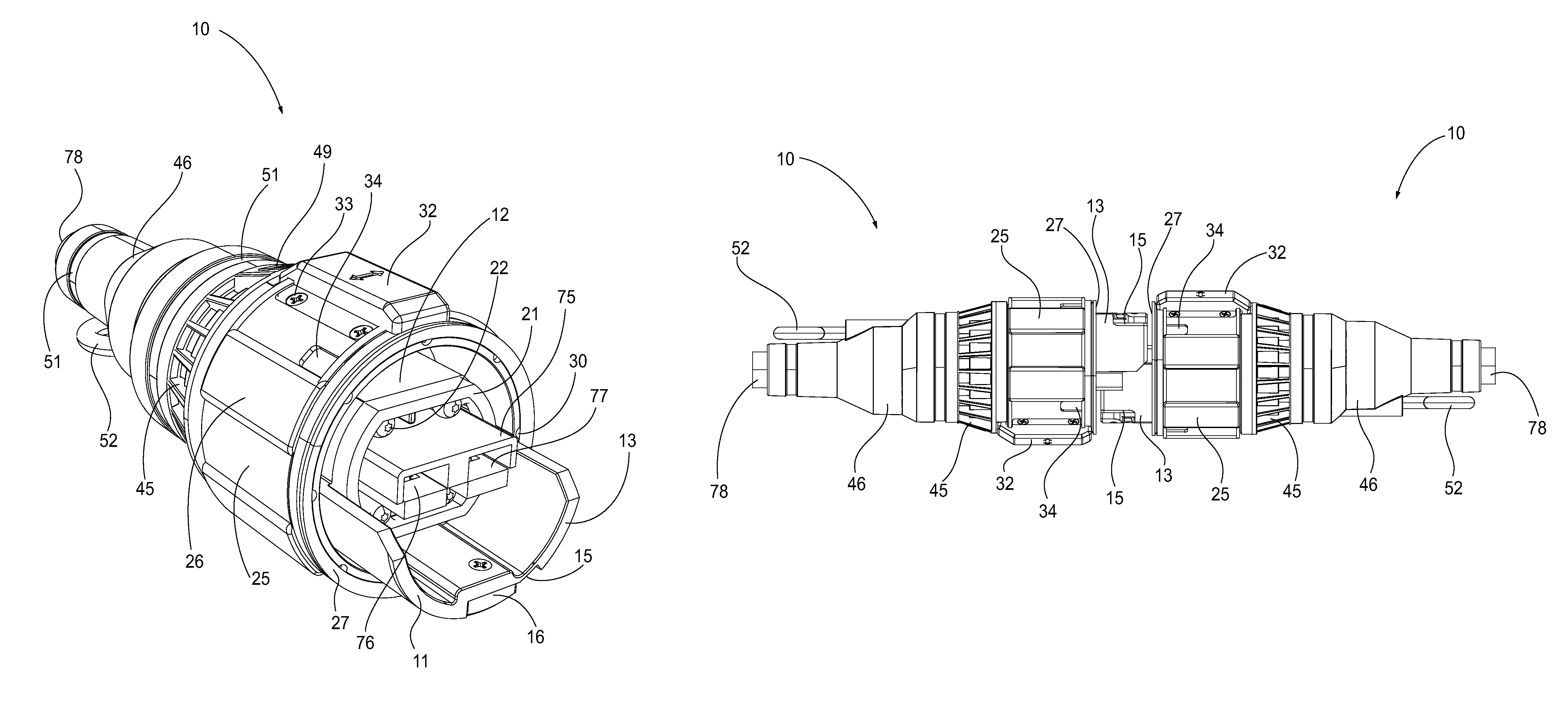
Two mating electrical power connector assemblies having identical configurations
a technology of electrical power connectors and connector assemblies, which is applied in the direction of coupling contacts, coupling devices, coupling bases/cases, etc., can solve the problems of difficult mating and un-mating, requiring a lot of force to operate the connectors, and affecting the use of operators, etc., to achieve the effect of improving the hermaphroditic electrical power connector assembly and being easy for operators to grip and handl
- Summary
- Abstract
- Description
- Claims
- Application Information
AI Technical Summary
Benefits of technology
Problems solved by technology
Method used
Image

Examples
Embodiment Construction
[0061]For purposes of the description hereinafter, the terms “end”, “upper”, “lower”, “right”, “left”, “vertical”, “horizontal”, “top”, “bottom”, “lateral”, “longitudinal”, and derivatives thereof shall relate to the invention as it is oriented in the drawing figures. However, it is to be understood that the invention may assume various alternative variations and step sequences, except where expressly specified to the contrary. It is also to be understood that the specific devices and processes illustrated in the attached drawings, and described in the following specification, are simply exemplary embodiments or aspects of the invention. Hence, specific dimensions and other physical characteristics related to the embodiments or aspects disclosed herein are not to be considered as limiting.
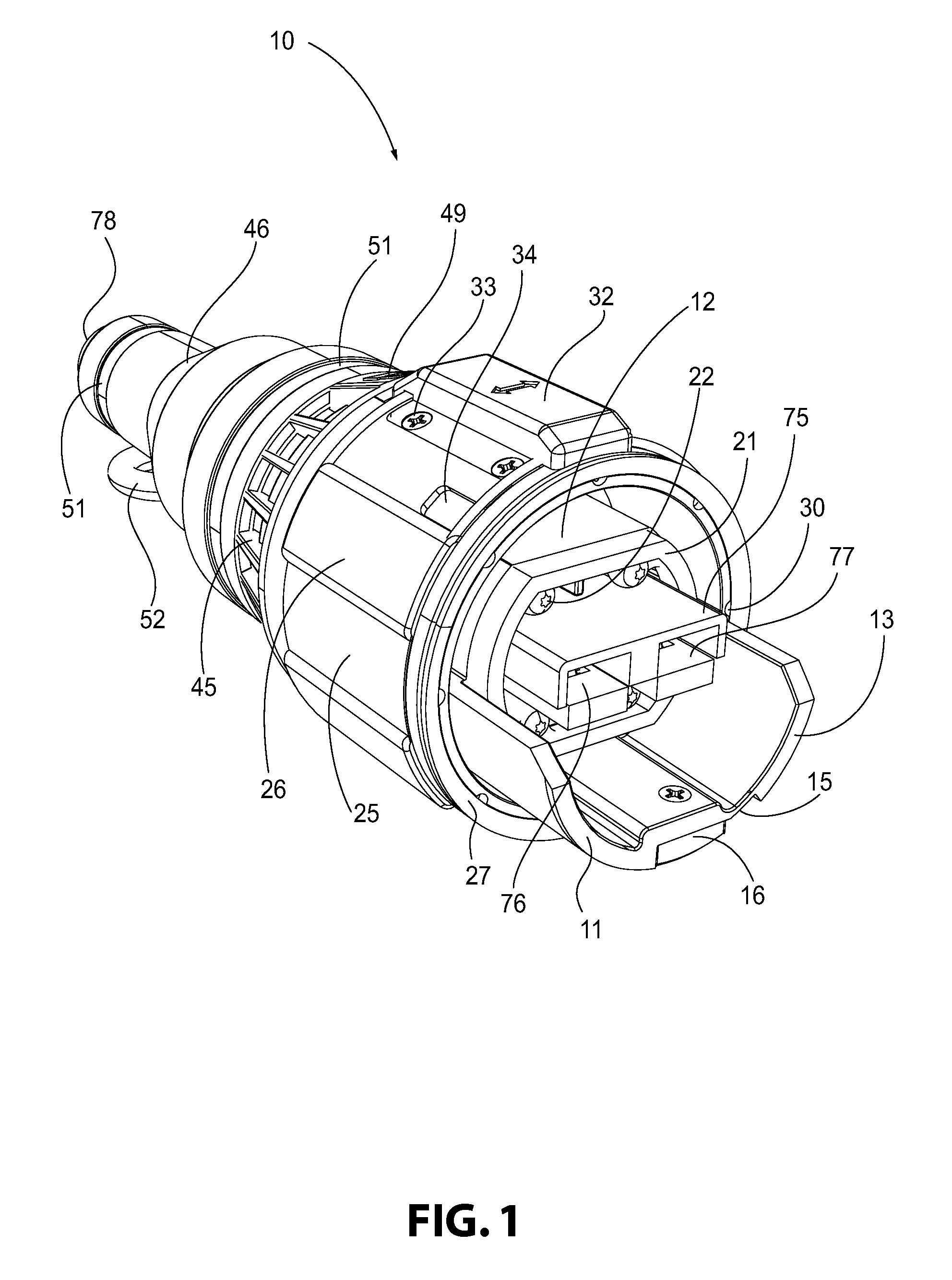
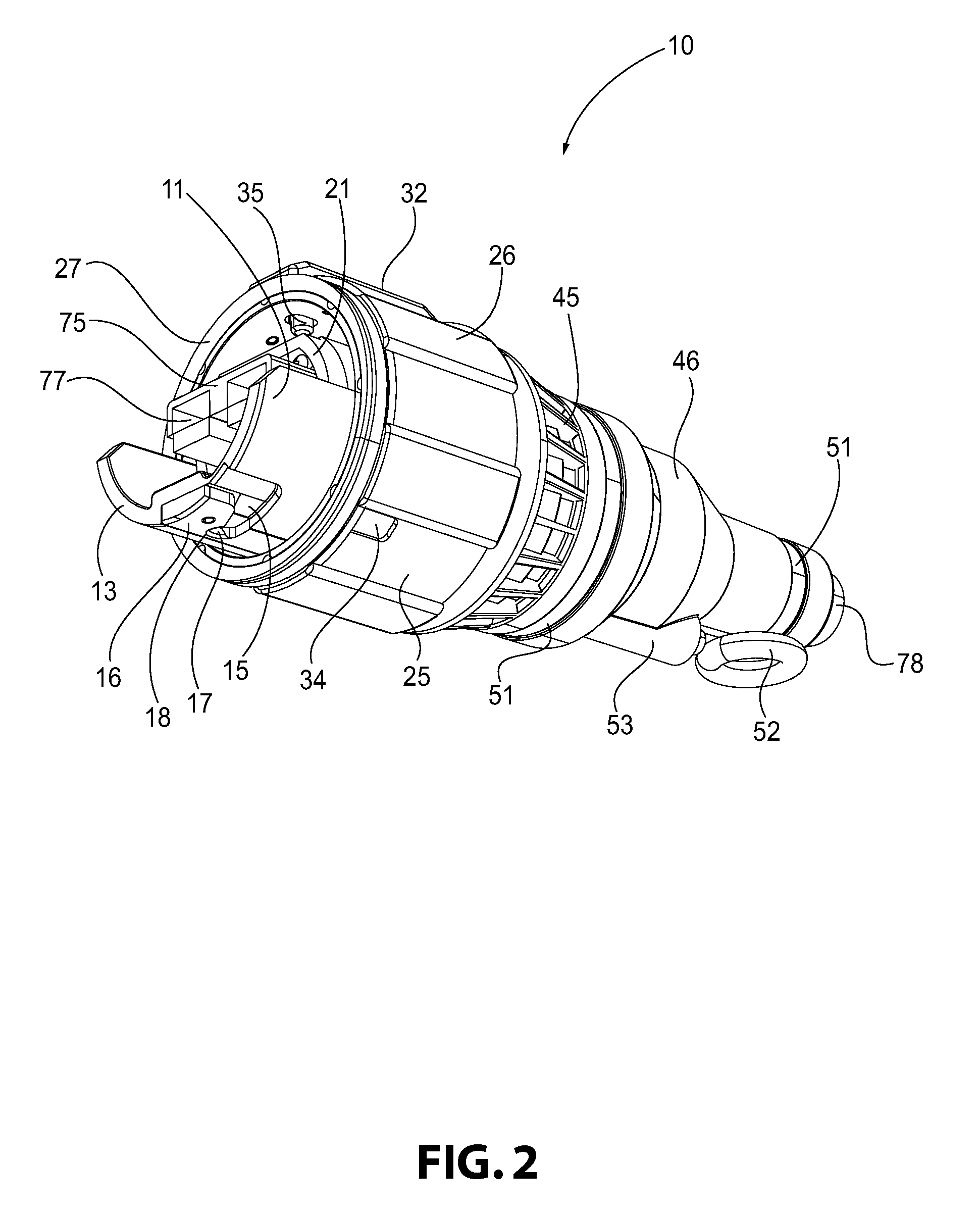
[0062]With reference to FIGS. 1-14C, a preferred and non-limiting embodiment or aspect of an electrical power connector assembly 10 in accordance with the principles of the present invention is sho...
PUM
 Abstract
Description
Claims
Application Information