Theft deterrent wheel fastener cap assembly and method

a technology of fastener cap and deterrent wheel, which is applied in the direction of pins, fastening means, domestic applications, etc., can solve the problems of professional defea

Inactive Publication Date: 2006-02-28
MAC LEAN FOGG CO
View PDF35 Cites 17 Cited by
  • Summary
  • Abstract
  • Description
  • Claims
  • Application Information

AI Technical Summary

Benefits of technology

[0007]It is another object to provide a new and improved wheel bolt or wheel nut and decorative cap assembly which functions as a theft deterrent.
[0008]Still another object...

Problems solved by technology

Although anti-theft lock mechanisms such as these are effective against amat...

Method used


Image

  • Theft deterrent wheel fastener cap assembly and method
  • Theft deterrent wheel fastener cap assembly and method
  • Theft deterrent wheel fastener cap assembly and method

Examples


Embodiment Construction

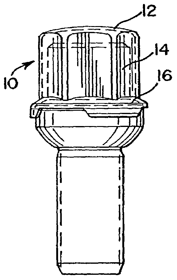
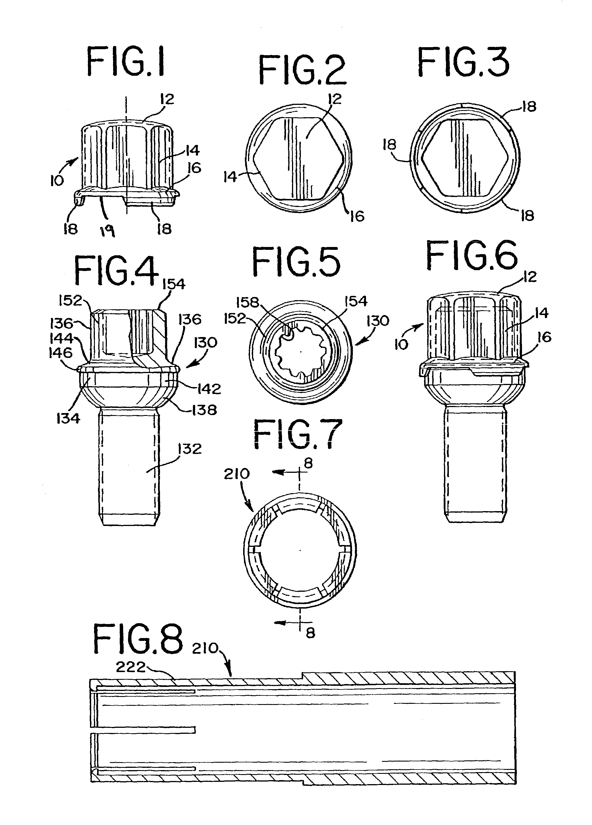
[0023]Referring now to the drawings, and particularly to FIGS. 1–3, a decorative cap for a vehicle wheel bolt or nut is seen generally at 10. The cap 10 is preferably formed in one piece from stainless steel sheet metal and includes a dome-shaped outer wall 12 and a generally cylindrical side wall 14 extending therefrom. A radially outwardly extending skirt 16 is formed around the inner end of the side wall 14.

[0024]The side wall 14 is polygonal in cross-sectional configuration so that it will appear to fit over the torque wrench gripping section of a wheel bolt head or wheel nut head in a manner hereinafter discussed. The skirt 16 has three identical locking lip segments 18 on its free inner edge 19, and extending slightly inwardly toward the center line CL of the cap 10. Each lip segment 18 extends around approximately 600 of the circumference of the skirt 16. The segments 18 are evenly spaced around the edge 19.

[0025]Referring now to FIGS. 4 and 5, a wheel bolt to which the cap 1...


PUM


Abstract

The present invention relates to a decorative cap for enclosing the head of a wheel bolt or wheel nut or the like which fastens a wheel to the hub of a vehicle, comprising an end closure wall, an endless side wall extending from an outer periphery of said end closure wall, a skid extending radially outwardly from a periphery of said side wall, and said skirt having a plurality of locking lips depending therefrom for releasably gripping the head.

Description

[0001]This application claims priority from U.S. provisional application Ser. No. 60 / 375,896, filed Apr. 26, 2002, entitled “THEFT DETERRENT WHEEL CAP ASSEMBLY AND METHOD.”RELATED APPLICATIONS[0002]This invention relates generally to wheel bolts or nuts for fastening a wheel to a vehicle hub. It relates particularly to a decorative cap for a theft deterrent bolt head or nut.BACKGROUND OF THE INVENTION[0003]Theft deterrence for automobile or truck wheels, for example, is sometimes provided with a key type removal mechanism. One of the plurality of wheel bolts or nuts has a unique keying feature incorporated, and the bolt or nut can only be removed with a key carried by the vehicle operator.[0004]Although anti-theft lock mechanisms such as these are effective against amateur thieves, professionals defeat them given a reasonable amount of time to do so. The present invention is designed to further thwart thieves seeking to remove vehicle wheels quickly.[0005]There are numerous decorati...

Claims


Application Information

Patent Timeline
IPC IPC(8): F16B37/14F16B41/00
CPCF16B41/005F16B37/14
Inventor WILSON, LARRY J.
Owner MAC LEAN FOGG CO
Why Eureka
Try Eureka