
Power transfer apparatus for concurrently transmitting data and power over data wires

a power transfer apparatus and data wire technology, applied in powerline communications applications, wireless systems/telephones, instruments, etc., can solve the problems of insufficient voice signal supported by pots for bandwidth intensive communications needs, and the difficulty of implementation of solutions

Inactive Publication Date: 2006-02-28
HEWLETT-PACKARD ENTERPRISE DEV LP
View PDF12 Cites 18 Cited by
  • Summary
  • Abstract
  • Description
  • Claims
  • Application Information

AI Technical Summary

Problems solved by technology

However, the voice signal supported by POTS is not sufficient for bandwidth intensive communications needs, such as, Ethernet communications.
Of course this requires that additional, unused wire pairs be available in the data cable, which may not always be available.
Also, if a change in the networking standard in the future dictates the use of the currently unused wire pairs in the networking cable, this solution becomes difficult to implement.

Method used


Image

  • Power transfer apparatus for concurrently transmitting data and power over data wires
  • Power transfer apparatus for concurrently transmitting data and power over data wires
  • Power transfer apparatus for concurrently transmitting data and power over data wires

Examples


Embodiment Construction

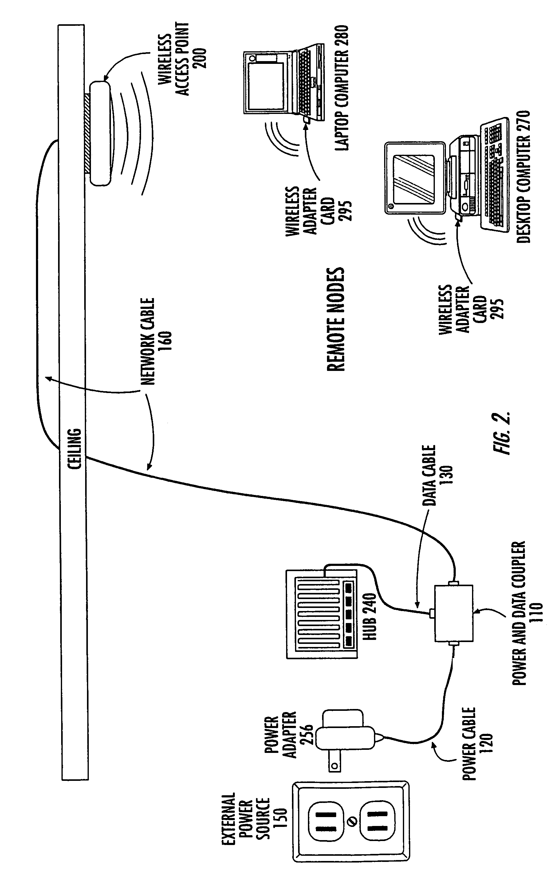
[0023]The following describes multiple embodiments of the invention. In one embodiment, power and data are combined and transmitted to a network device such as a wireless access point. The wireless access point uses the power signal to power communication circuits for communicating with wireless network nodes. Because the power and data are combined, the installation of the wireless access point is simplified and may reduce the cost of installing the wireless access points.

Power Transfer Apparatus Overview

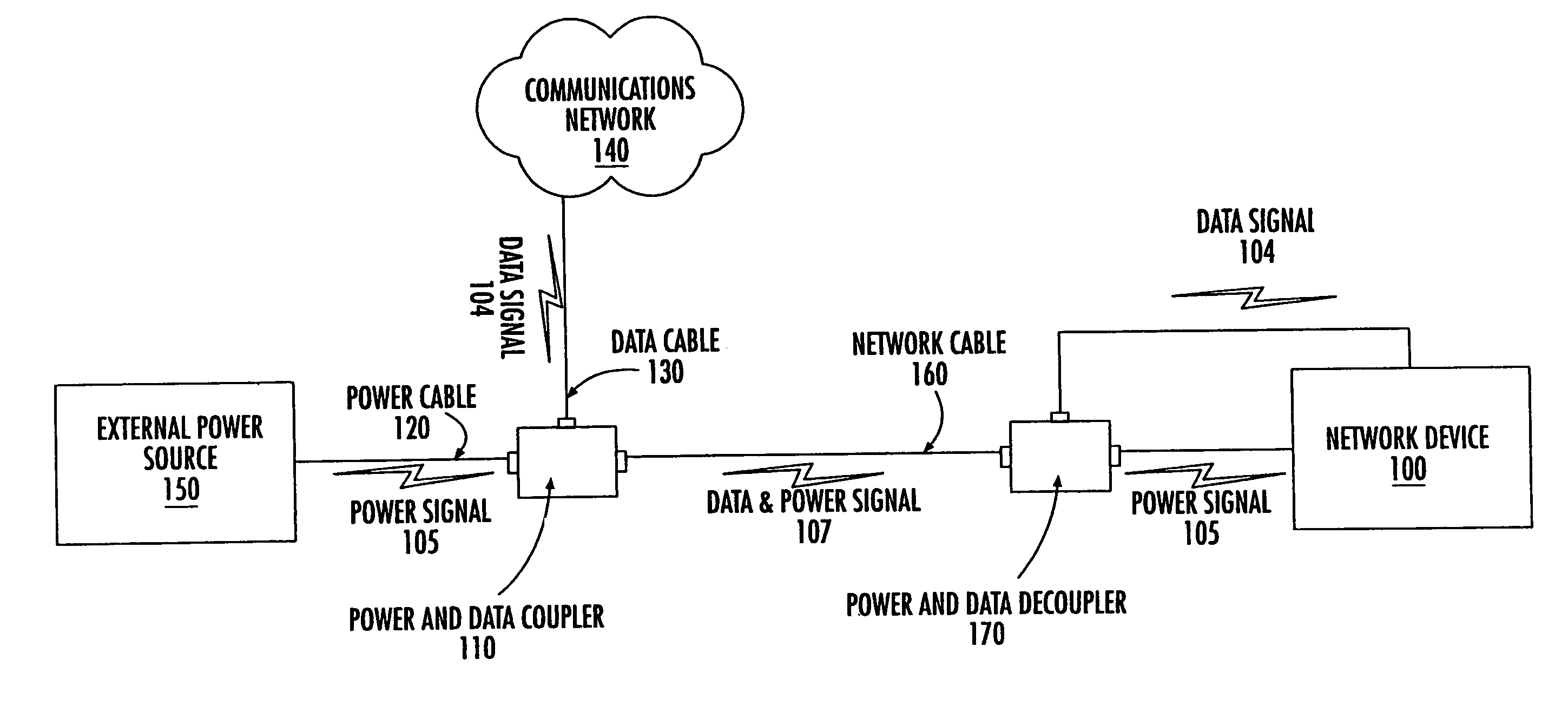
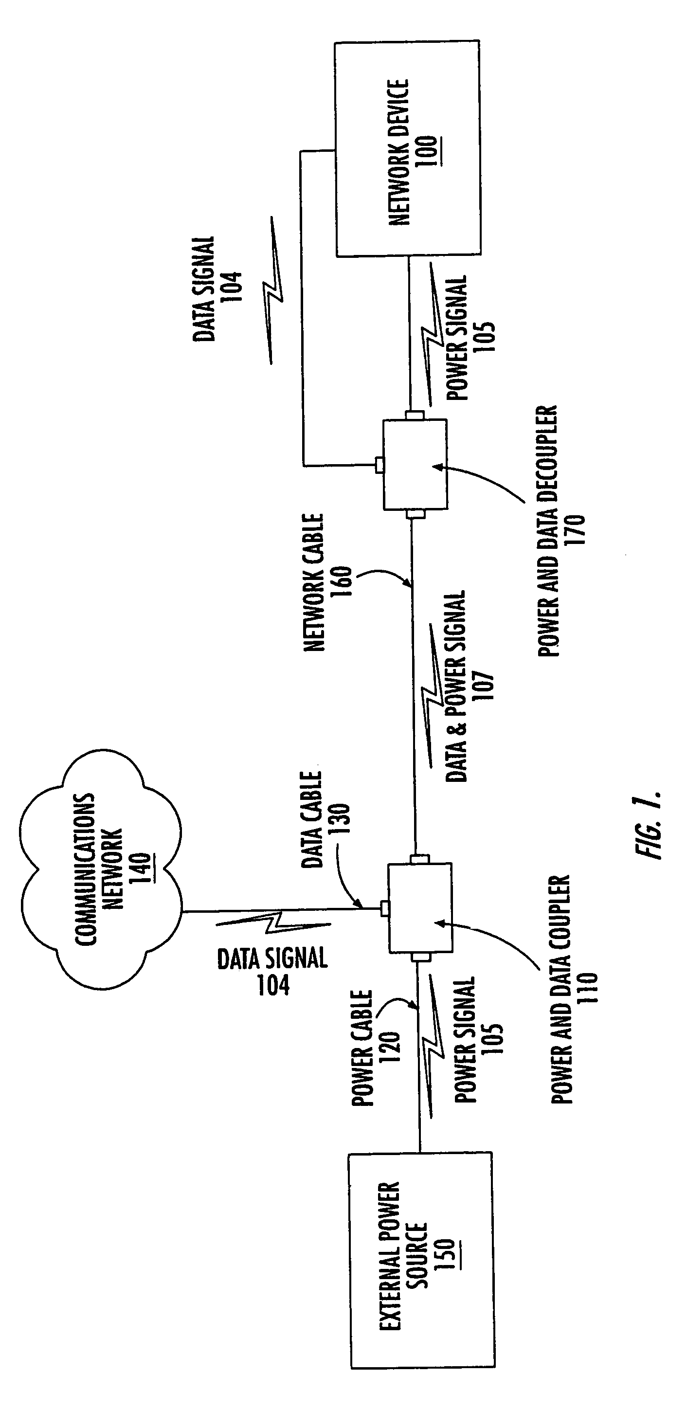
[0024]FIG. 1 shows the overall configuration of one embodiment of the invention including a power transfer apparatus. The following lists the elements in FIG. 1 and then describes those elements.

[0025]FIG. 1 includes the following elements: an external power source 150; a power cable 120; a data cable 130; a power and data coupler 110; a network cable 160; a power and data decoupler 170; and, a network device 100.

[0026]The following describes the coupling of the elements of FIG. 1....


PUM


Abstract

Power supply current, sufficient to power a remote network device, is transmitted concurrently with a network data signal over a transmission line. A power-sourcing network device that can include a coupling circuit provides power and data to the remote network device. The remote network device (which can be a wireless access point) can separate the power signal from the data signal and use the power supply current to further process or retransmit the data signal. The power signal may be a low frequency relative to the frequency of the data signal, or it may be DC.

Description

CROSS REFERENCE TO RELATED APPLICATIONS[0001]This Application is a continuation of application Ser. No. 10 / 281,778, filed on Oct. 28, 2002, now U.S. Pat. No. 6,753,761; which is a continuation of application Ser. No. 09 / 974,237, filed Oct. 10, 2001, now U.S. Pat. No. 6,496,105, issued Dec. 17, 2002; which is a continuation of application Ser. No. 09 / 675,730, filed Sep. 29, 2000, now U.S. Pat. No. 6,329,906, issued Dec. 11, 2001; which is a continuation of application Ser. No. 09 / 416,067, filed Oct. 12, 1999, now U.S. Pat. No. 6,140,911, issued Oct. 31, 2000; which is a continuation of application Ser. No. 08 / 865,016, filed May 29, 1997, now U.S. Pat. No. 5,994,998, issued Nov. 30, 1999.BACKGROUND OF THE INVENTION[0002]1. Field of the Invention[0003]The invention relates in general to the field of data networking and communications, and in particular to interconnecting computers to a local area network (“LAN”) or a wide area network (“WAN”) through data lines that also carry power.[0...

Claims


Application Information

Patent Timeline
Patent Type & Authority Patents(United States)
IPC IPC(8): H04B1/00G08C19/00H04B3/54H04L12/10
CPCH04B3/542H04L12/10H04B2203/5437H04B2203/5441H04B2203/547H04B2203/5483H04B2203/5491H04B2203/5445
Inventor FISHER, DAVID A.BURNS, LAWRENCE M.MUTHER, STEPHEN E.
Owner HEWLETT-PACKARD ENTERPRISE DEV LP
Learn More