Method and device for grinding a rotating roller using an elastic steady-rest support

a technology of elastic steady-rest support and rotating roller, which is applied in the direction of grinding machine components, grinding machines/tools, grinding machines, etc., can solve the problem that the prescription should not be interpreted as strict in geometric terms, and achieve the effect of reducing the surface quality

Inactive Publication Date: 2006-03-07
ERWIN JUNKER MASCHNINENFAB
View PDF18 Cites 6 Cited by
  • Summary
  • Abstract
  • Description
  • Claims
  • Application Information

AI Technical Summary

Benefits of technology

[0009]In that the cushioned body is positioned in the circumferential region opposite the grinding wheel against the roller to be ground, the transverse vibrations of the roller and even to an extent the vibrations deriving from the grinding wheel are successfully damped. The regenerative chattering does not occur, and thus there are no longer any feared chatter marks. That is, in contrast to the rests or supports comprising steel, the cushioned body does not lead to any tracks that result in reduced surface quality and are immediately recognizable to one skilled in the art. Prescribing the circumferential region opposite the grinding wheel means that the cushioned body is to be positioned approximately radially opposite the grinding wheel on the other side of the roller. However, this prescription should not be interpreted to be strict in geometric terms, because it is possible to successfully reduce vibrations even when the location at which the cushioned body is positioned against the roller is differs radial...

Problems solved by technology

However, this prescription should not be interpreted to be strict in geometric terms, because it is possible to successfully reduce vibrations even when...

Method used


Image

  • Method and device for grinding a rotating roller using an elastic steady-rest support
  • Method and device for grinding a rotating roller using an elastic steady-rest support
  • Method and device for grinding a rotating roller using an elastic steady-rest support

Examples


Embodiment Construction

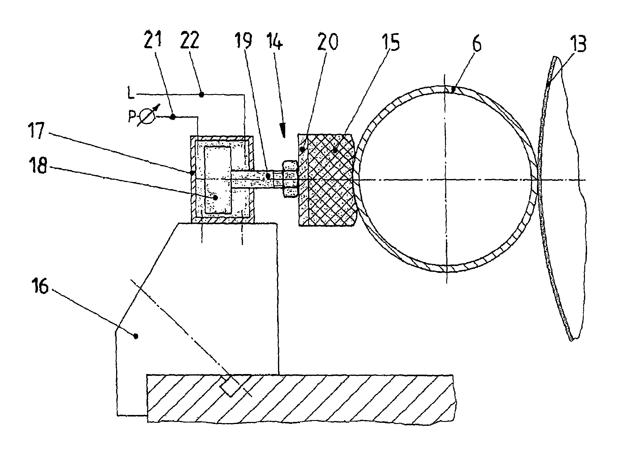
[0012]The following advantageous embodiments of the inventive method are related to how the cushioned body—hereinafter collectively referred to as flexible cushion—is positioned against the roller and moved in relation to it.

[0013]Thus, it has proved advantageous that the cushion 15 is positioned elastically flexible against the roller 6. In the simplest case, this can occur using a linear guide with a positioning set spring, the tension of which is adjustable. Preferably, however, it is positioned using a pressure medium, but electronically controlled positioning using electromotors is also conceivable.

[0014]There are broad options for applications and the positioning force with which the flexible cushion 15 is positioned against the roller 6 is adjustable and can even equal a value of 0 prior to the beginning of the grinding process. Positioning of the at least one flexible cushion occurs because the roller bends outward in the direction of cushion under the influence of the proce...


PUM

PropertyMeasurementUnit
Forceaaaaaaaaaa
Pressureaaaaaaaaaa
Lengthaaaaaaaaaa

Abstract

The invention relates to a device for grinding rollers, also for grinding hollow rollers. As the rollers tend to vibrate transversally as a result of the contact with the grinding disc, a cushioned body is applied to the opposite side of the roller from the grinding disc, said body being engaged pneumatically against the roller and adapting at least partially to the contours of the roller. The cushioned body consists of an elastic solid material or an elastic external skin that is filled with an elastic pressurized medium. The engagement pressure of the cushion is adjustable. This is achieved by a pneumatic advance cylinder located on a base, said cylinder having a piston that can be impinged on both sides and that bears on its piston rod a fixing plate comprising the elastic cushion. The advance cylinder is connected to compressed air conduits, P indicating the conduit comprising a pressure regulator and L indicating the return conduit in the standard case. The invention thus provides a device for damping vibrations, which suppresses any regenerative chatter and guarantees a grinding pattern that is devoid of chatter marks.

Description

BACKGROUND OF THE INVENTION[0001]The invention relates to a method and an apparatus for grinding the exterior circumference of a rotating roller, held at its ends, with a rotating grinding wheel, whereby the length of the roller is a multiple of the width of the grinding wheel.[0002]In many large-scale and industrial production processes, long narrow rollers are required that rotate during operation, sometimes must be driven, and often must be heated or cooled from inside. Such rollers can for instance have a length of approximately 1000 mm and a diameter of 85 mm. In addition the rollers are frequently tube-shaped with a low wall thickness that can be less than 1 mm. High stresses are placed on the surface quality of these rollers and on their dimensional stability. Grinding such rollers to final dimensions and the required surface quality therefore present great challenges to one skilled in the art.[0003]One known disadvantageous aspect when grinding the exterior of rollers is tha...

Claims


Application Information

Patent Timeline
IPC IPC(8): B24B49/00B24B41/06
CPCB24B41/065
Inventor JUNKER, ERWIN
Owner ERWIN JUNKER MASCHNINENFAB
Why Eureka
Try Eureka