Heat sink clip with pressing post

a heat sink and post technology, applied in the direction of cooling/ventilation/heating modifications, semiconductor/solid-state device details, semiconductor devices, etc., can solve the problems of invariable resilient compressing force, clip lack of adaptability for use in various applications having different force requirements, and the resilient compressing force tends to diminish

Inactive Publication Date: 2006-03-07
HON HAI PRECISION IND CO LTD
View PDF9 Cites 65 Cited by
  • Summary
  • Abstract
  • Description
  • Claims
  • Application Information

AI Technical Summary

Benefits of technology

[0006]Accordingly, an object of the present invention is to provide a heat sink clip which is durable, and which is capable of providing an adaptable compressing force for securely attaching a heat sink to an electronic package in a variety of applications.

Problems solved by technology

However, the resilient compressing force is invariable because it is provided only by the deformation of the clip.
Therefore the clip lacks adaptability for use in various applications having different force requirements.
Furthermore, the resilient compressing force tends to diminish over time due to fatigue.

Method used


Image

  • Heat sink clip with pressing post
  • Heat sink clip with pressing post
  • Heat sink clip with pressing post

Examples


Embodiment Construction

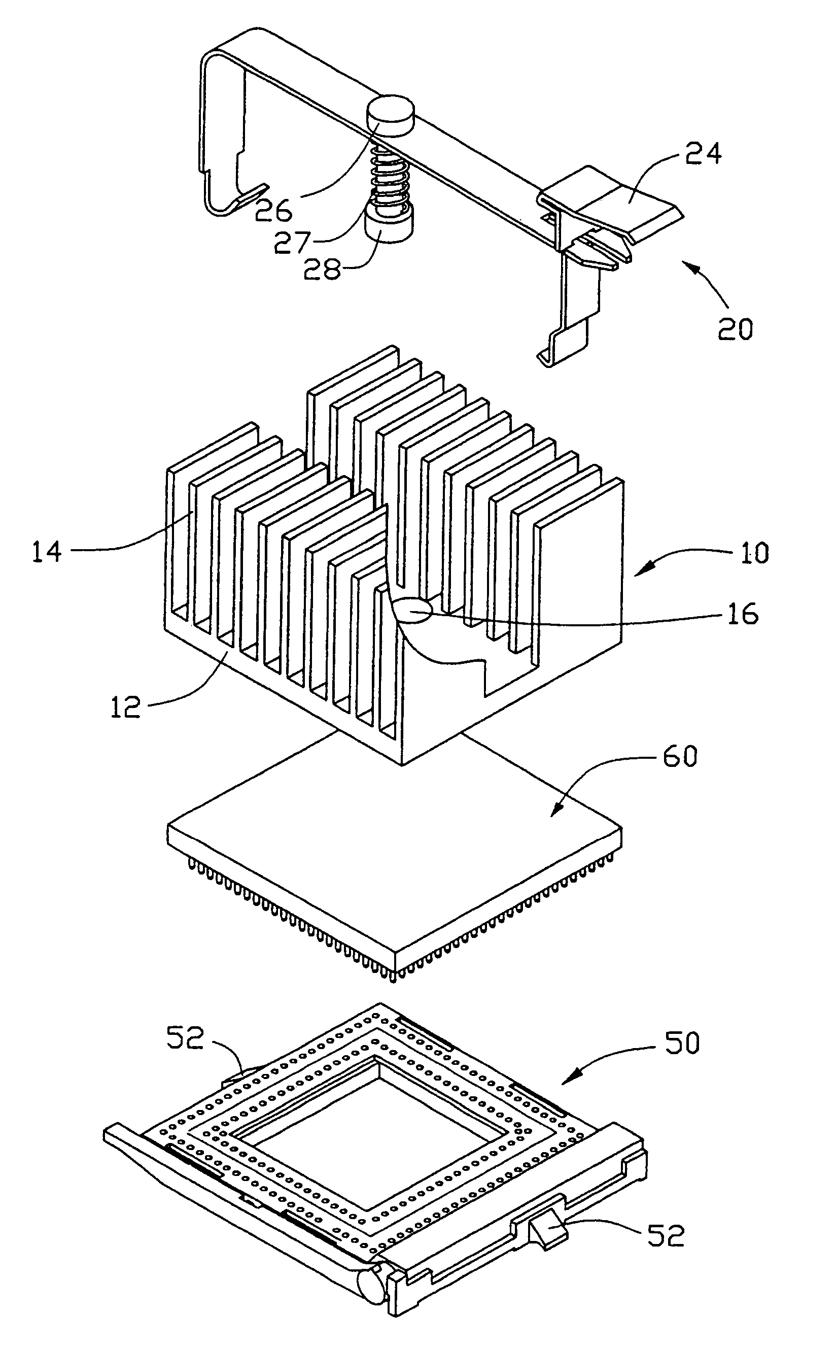
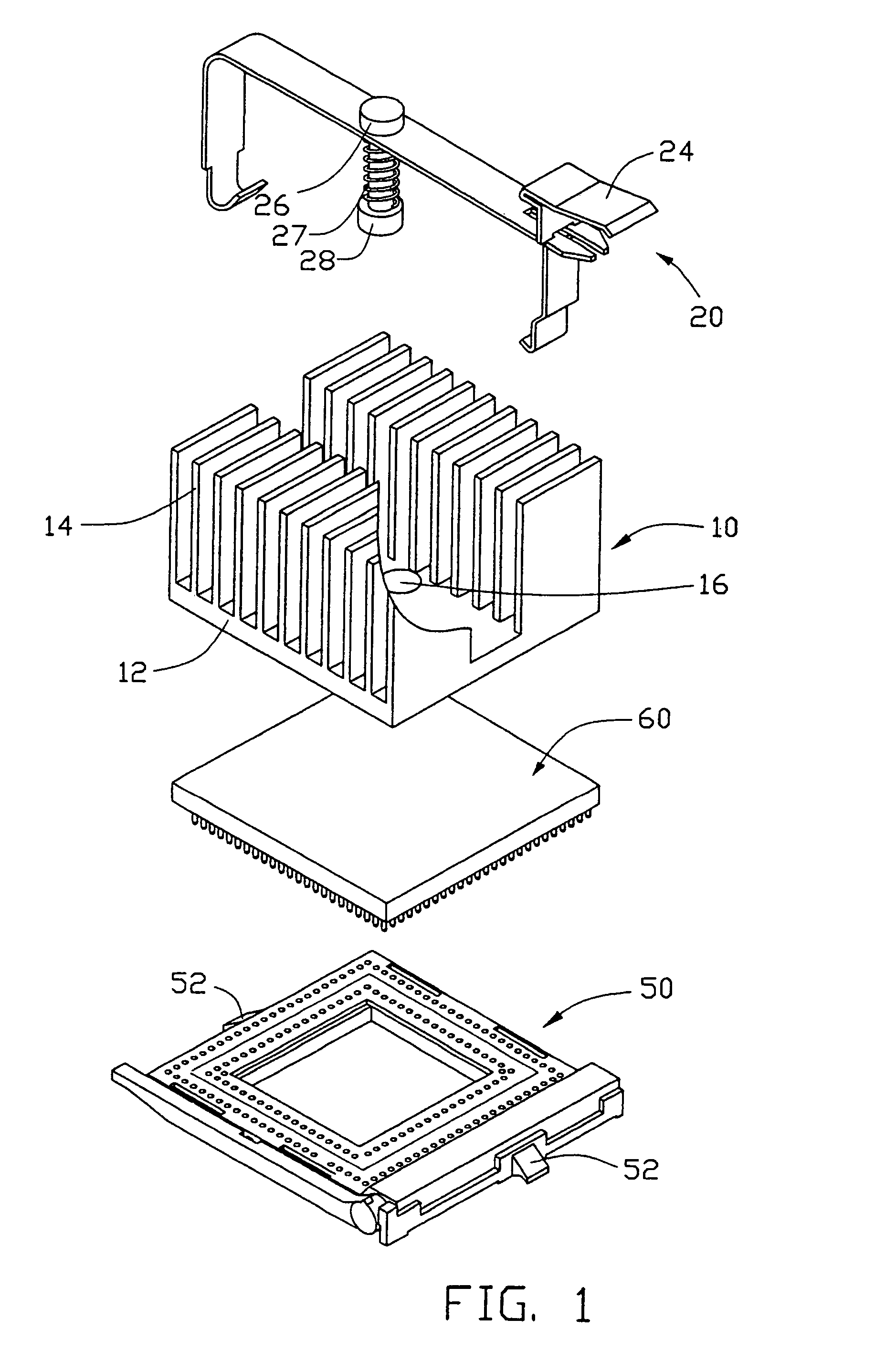
[0015]Referring to FIG. 1, a heat sink clip 20 in accordance with the preferred embodiment of the present invention is used to press a heat sink 10 onto a CPU 60 mounted on a socket 50. The heat sink clip 20 comprises a main body (not labeled), a post 26, and a spring 27.

[0016]The heat sink 10 comprises a base 12, and a plurality of fins 14 extending upwardly from the base 12. A channel (not labeled) is defined in a middle of the heat sink 10. A blind hole 16 is defined in a top surface (not labeled) of the base 12 in the channel. The socket 50 forms two catches 52 at opposite sides thereof respectively, corresponding to opposite ends of the channel of the heat sink 10.

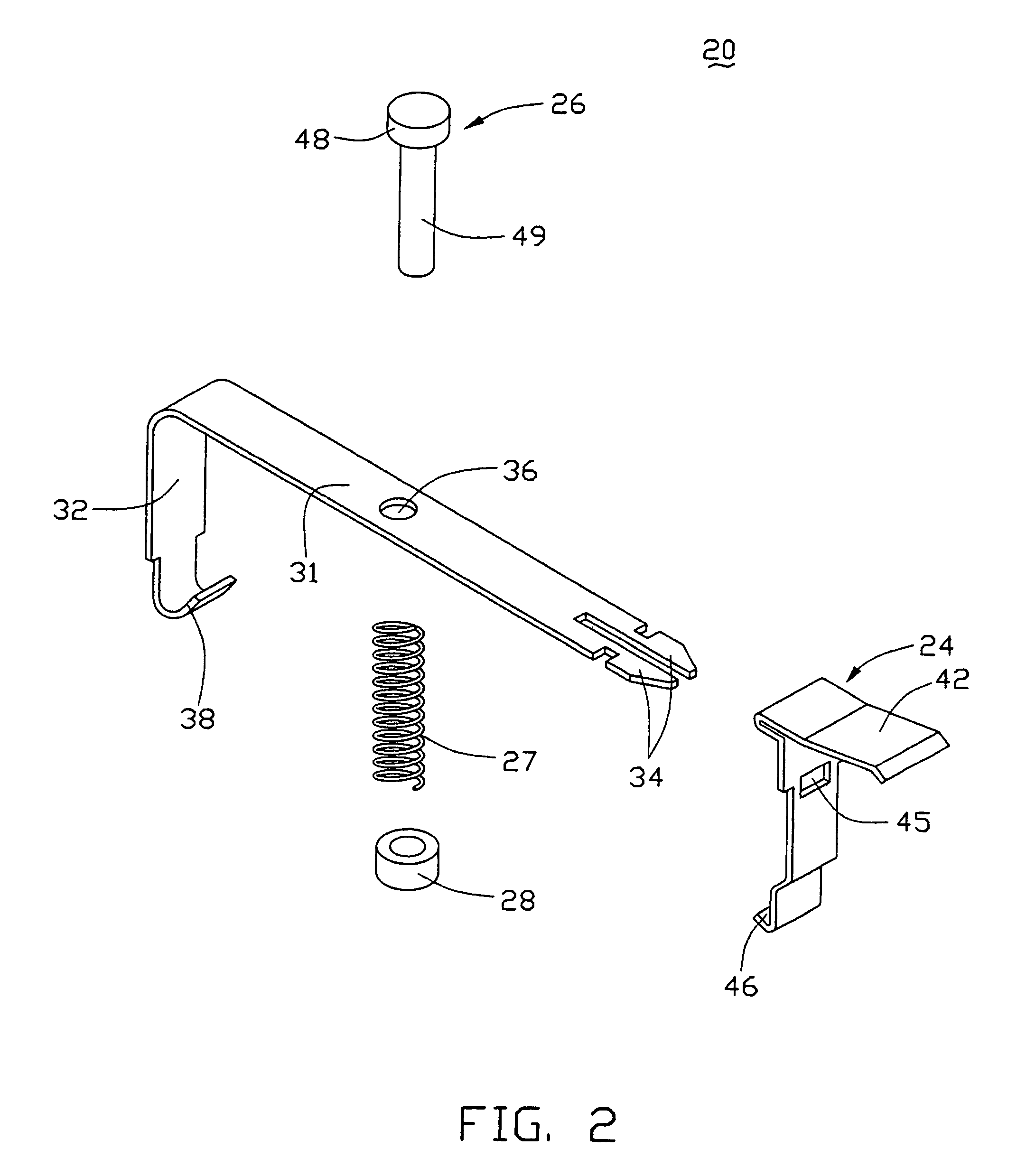
[0017]Referring to FIG. 2, the main body of the clip 20 comprises a longitudinal portion 31, and a first locking arm 32 and a second locking arm 24. The first locking arm 32 integrally extends downwardly from a first end of the longitudinal portion 31. The second locking arm 24 is detachably fixed to and extends downw...


PUM


Abstract

A heat sink clip (20) includes a main body, a post (26), and a spring (27). The main body includes a longitudinal portion (31), first and second locking arms (32, 24) extending downwardly from opposite ends of the longitudinal portion. The longitudinal portion defines a through aperture (36) in a middle thereof. Two hooks (38, 46) are respectively formed at free ends of the first and second locking arms for engagement with catches (52) of a socket (52). The post has a pressing portion at a bottom thereof for being fittingly received in a blind hole (16) of a heat sink (10). The post extends through the through aperture of the longitudinal portion. The resilient element is disposed around the post below the longitudinal portion.

Description

BACKGROUND OF THE INVENTION[0001]1. Field of the Invention[0002]The present invention relates to securing of heat sinks to electronic packages; particularly to a heat sink clip capable of providing an adaptable compressing force applied to a heat sink for securely and readily retaining the heat sink to an electronic package, and a heat sink assembly employing such a heat sink clip.[0003]2. Related Art[0004]In order to reduce heat produced by high-speed computer Central Processing Units (CPUs) such as the Pentium IV produced by Intel(R) and the K8 produced by AMD(R), bigger and heavier heat sinks are becoming increasingly necessary. Strong resilient clips are often used to attach these heat sinks onto electronic packages.[0005]An example of this kind of heat sink clip is disclosed in Taiwan patent publication No. 456586. The clip is usually integrally formed from a sheet of plastic or steel. The clip comprises a central pressing portion, and two resilient portions extending outwardly...

Claims


Application Information

Patent Timeline
Patent Type & Authority Patents(United States)
IPC IPC(8): H05K7/20H01L23/40
CPCH01L23/4093H01L2924/0002H01L2924/00
Inventor LEE, HSIEH KUNXIA, WELLINTLEE, TOLYWANG, GEN-CAI
Owner HON HAI PRECISION IND CO LTD
Why Eureka
Try Eureka