Multi-purpose processing chamber with removable chamber liner

a processing chamber and removable technology, applied in the direction of electric discharge tubes, coatings, chemical vapor deposition coatings, etc., can solve the problems of imposing substantial capital costs on fabrication equipment and other costs, affecting the uniformity and efficiency of exhaust systems, and the inability to reconfigure the processing chamber on a platform to perform other processes

Inactive Publication Date: 2006-03-14
APPLIED MATERIALS INC
View PDF17 Cites 37 Cited by
  • Summary
  • Abstract
  • Description
  • Claims
  • Application Information

AI Technical Summary

Benefits of technology

This patent describes a device that has three different areas: a processing area, an exhaust area, and a pass-through area. These areas can be adjusted by simply replacing a part called the chamber liner. There are also traps in the pass-through area to keep any plasma from leaking out of the processing area.

Problems solved by technology

The technical problem addressed in this patent is the high cost and limitations of current fabrication platforms used for manufacturing integrated circuits. These platforms require replacing entire structures even if only one process needs to change, leading to significant expenses. Additionally, existing processing chambers struggle with uneven purging of process gases due to their design and configuration, resulting in inconsistent processing results. There is a need for a versatile chamber capable of efficiently and uniformly removing processing gases while providing flexibility for various types of processes.

Method used


Image

  • Multi-purpose processing chamber with removable chamber liner
  • Multi-purpose processing chamber with removable chamber liner
  • Multi-purpose processing chamber with removable chamber liner

Examples


Embodiment Construction

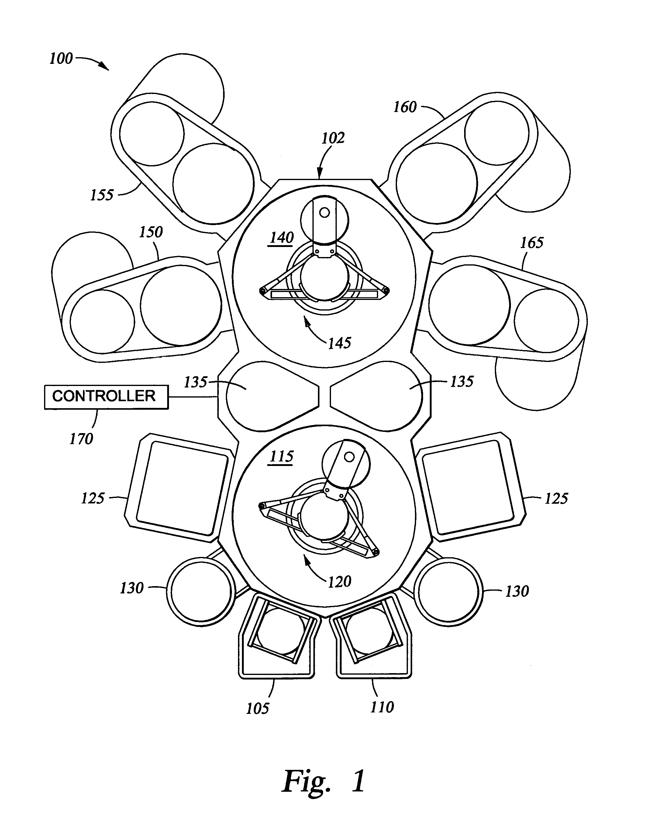
[0023]FIG. 1 is a schematic view of a cluster tool system having a plurality of substrate processing chambers. The cluster tool system 100 is a two-staged vacuum processing system defined by a mainframe or platform 102 having a plurality of modules or chamber attached thereto. An example of a commercial embodiment of a two-staged vacuum processing platform is the Endura® platform, available from Applied Materials, Inc., Santa Clara, Calif., which is described in U.S. Pat. No. 5,186,718, Tepman et al., hereby incorporated by reference in its entirety.

[0024]The cluster tool system 100 includes vacuum load-lock chambers 105 and 110 attached to a first stage transfer chamber 115. The load-lock chambers 105 and 110 maintain vacuum conditions within the first stage transfer chamber 115 while substrates enter and exit system 100. A first robot 120 transfers substrates between the load-lock chambers 105 and 1110 and one or more substrate processing chambers 125 and 130 attached to the first...


PUM

PropertyMeasurementUnit
Fractionaaaaaaaaaa
Fractionaaaaaaaaaa
Diameteraaaaaaaaaa

Abstract

A multi-purpose chamber that can be configured for a variety of processes, including deposition processes and etch processes, for example, by installing one or more removable chamber liners. The multi-purpose chamber provides uniform plasma confinement around a substrate disposed in the chamber for various processing conditions. The multi-purpose chamber also provides efficient and uniform exhaust of processing gas from the chamber.

Description


Claims


Application Information

Patent Timeline
Owner APPLIED MATERIALS INC
Why Eureka
Try Eureka