Method of manufacturing in-line roller skate with detachable boot

Inactive Publication Date: 2006-03-21
LANGE INTERNATIONAL SA
View PDF8 Cites 0 Cited by
  • Summary
  • Abstract
  • Description
  • Claims
  • Application Information

AI Technical Summary

Benefits of technology

[0008]According to an embodiment with a non-releasable but detachable boot, the rigid insole extends from the heel to the front end of the boot and is fixed to the platforms of the chassis by screws resting on the insole. In order to detach the boot from the chassis all that is therefore required is for the comfort sole covering the insole to be removed and the screws unscrewed. It is thus easily possible to replace the boot with a boot of a different size or to replace a damaged boot. Such a boot can be used with a standard chassis like those available commercially.

Problems solved by technology

Such a construction does not allow the boot to be detached from the chassis, for example to replace the boot by a boot of a different size.
As the practice of roller skating is essentially a summer sport, the front part of the cradle, which surrounds and covers the front of the foot, is perforated to allow air to the foot, but in spite of this the ventilation is often insufficient.
What is more, while it is true that the flexible boot is pressed against the bottom and sides of the cradle, it can however move and deform in the cradle, which means that the connection between foot and skate is not as good as it is in a fixed-boot skate.

Method used


Image

  • Method of manufacturing in-line roller skate with detachable boot
  • Method of manufacturing in-line roller skate with detachable boot
  • Method of manufacturing in-line roller skate with detachable boot

Examples


first embodiment

[0034]In this embodiment, the boot 30 has a short upper, the structure of this upper being similar to that of the upper of the boot 1 of the first embodiment, as is clear in FIG. 4. The boot 30 is equipped with a rigid footbed 31, again preferably made of plastic, with a longitudinal profile in the form of an upturned and curved dish extending from the heel to approximately the middle of the sole and covered with a comfort inner sole 32. From the middle of the boot forward, the sole consists of a flexible insole 33 and of a rubber sole 34. Under the footbed 31, the sole consists of relatively thick rubber 35. The boot 30 is therefore flexible forward of the rigid insole 31, which allows for easy walking.

[0035]The front end of the insole 31 has a projection 36 interacting with an attachment member 37 secured to the front platform 38 of the chassis 39 of the skate. The rear end 31a of the insole 31 projects out of the boot and has ratchet-teeth toothing 40 interacting with the nose 41...

third embodiment

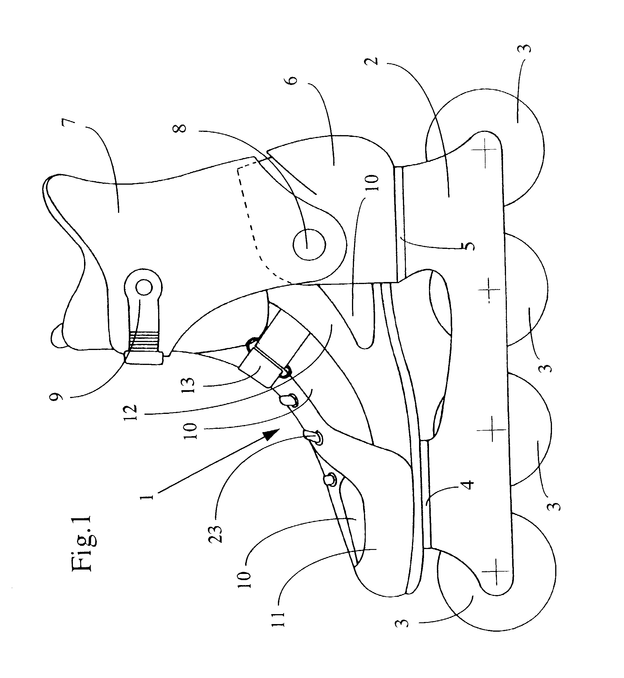
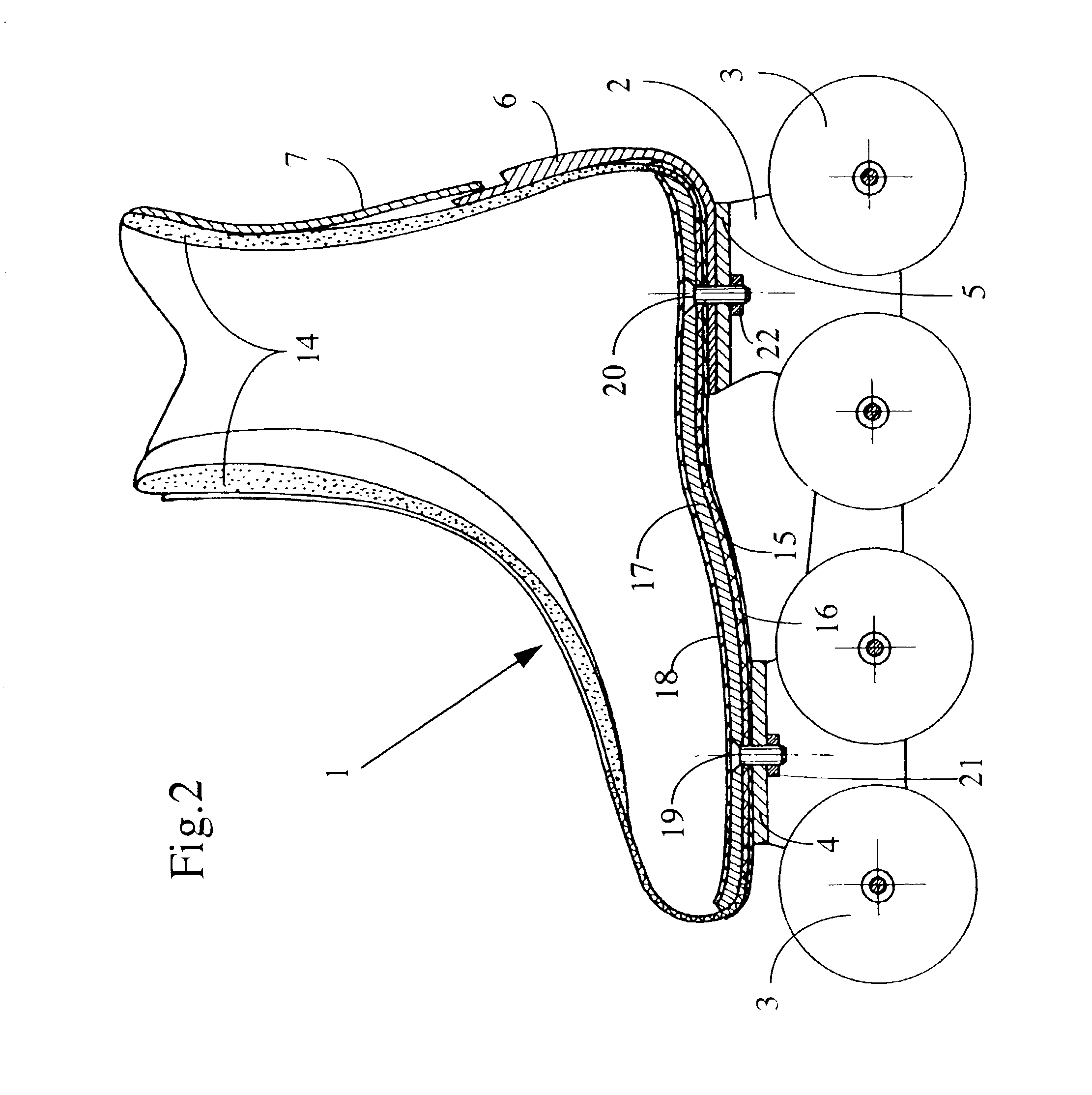
[0041]A third embodiment will now be described with reference to FIGS. 7 to 10.

[0042]With a view to avoiding needless repetition, the elements which are taken again from the first embodiment have been denoted by the same reference numerals.

[0043]Externally, the skate depicted in FIG. 7 differs from the skate depicted in FIG. 1 only in the presence, at the front, of a cap 54 fixed to the front platform 4 and enveloping the end of the foot.

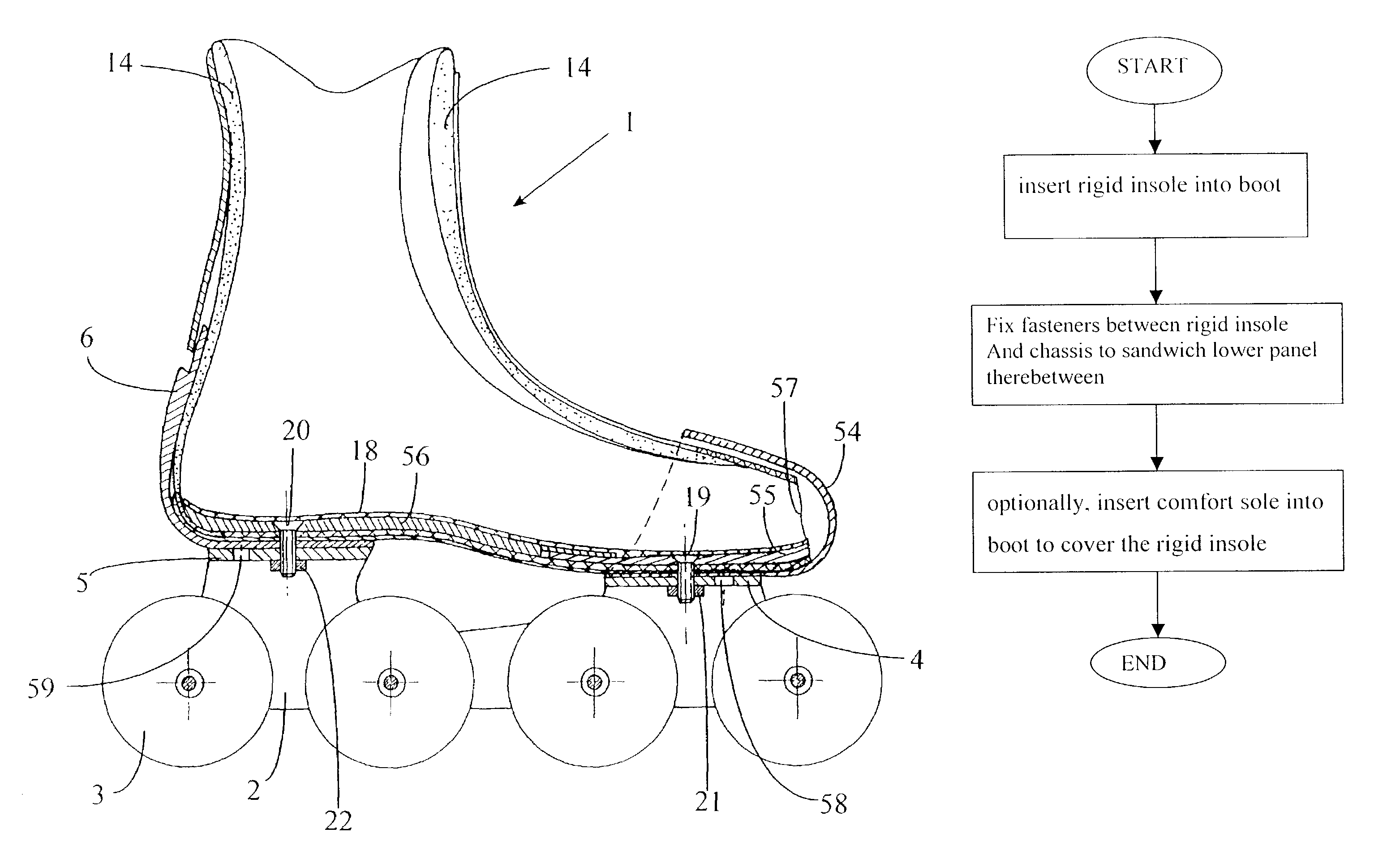
[0044]By contrast, on the inside, as can be seen in FIG. 8, the boot of this third embodiment differs from the first embodiment in that, on the one hand, the rigid insole is made up of two parts 55 and 56 which overlap one another between the points at which the insole is fixed to the platforms 4 and 5 and, on the other hand, in that the front end 57 of the boot upper is open, the boot here being closed by the cap 54. The front platform 4 has at least one second hole 58 situated forward of the hole through which the fixing screw 20 passes on the axi...


PUM


Abstract

A method of fabricating an in-line roller skate is provided. The in-line roller skate has a chassis (2;39) equipped with at least two rollers (3) and two platforms (4, 5; 34; 47) and a boot (1; 30). The boot has a supple upper connected to a lower panel and is capable of enclosing a wear's foot. The method includes the steps of (a) inserting a rigid insole (17; 31, 50; 55; 56) into the boot; (b) fixing fasteners between the rigid insole and the chassis, thus sandwiching the lower panel therebetween; and (c) optionally, inserting a comfort sole into the boot to cover the rigid insole.

Description

REFERENCE TO RELATED APPLICATIONS[0001]This application is a division application of U.S. application Ser. No. 09 / 218,843, filed Dec. 22, 1998, now U.S. Pat. No. 6,557,864 entitled “IN-LINE ROLLER SKATE”, which claims priority to Swiss Patent Application no. 2 973 / 97, filed Dec. 24, 1997, the contents of which are incorporated herein by reference thereto.FIELD OF THE INVENTION[0002]The invention relates to an in-line roller skate consisting of a chassis equipped with at least two rollers and having two platforms and with a boot with a flexible upper resting on the platforms and connected to the chassis by a rigid part.PRIOR ART[0003]U.S. Pat. No. 5,437,466 discloses an in-line roller skate the boot of which consists of a flexible upper bonded to a rigid base, itself welded to the chassis or forming an integral part of this chassis. Such a construction does not allow the boot to be detached from the chassis, for example to replace the boot by a boot of a different size.[0004]U.S. Pat...

Claims


Application Information

Patent Timeline
IPC IPC(8): A63C1/04A43B3/26A43B5/16A43B13/12A63C17/06A63C17/14
CPCA43B3/26A43B5/1608A43B5/1625A43B5/1641A43B13/026A63C17/0086A63C17/061A63C17/062A63C17/1418A43B13/12A63C2017/1481
Inventor LENOIR, DAVID
Owner LANGE INTERNATIONAL SA
Why Eureka
Try Eureka