Attachment coupling device for heavy machinery

a technology for attachment coupling and heavy machinery, which is applied in the direction of couplings, mechanical machines/dredgers, manufacturing tools, etc., can solve the problems of difficult connecting pins and the like, cumbersome and laborious coupling operations of conventional attachment coupling structures, and difficulty in transportation and handling attachments, etc., to achieve quick and convenient connection of attachments

Inactive Publication Date: 2006-03-21
HANWOO TNC CORP
View PDF8 Cites 56 Cited by
  • Summary
  • Abstract
  • Description
  • Claims
  • Application Information

AI Technical Summary

Benefits of technology

[0014]With the afore-mentioned problems inherent in the prior art taken into account, it is an object of the present invention to provide an attachment coupling device for such heavy machinery as excavators that allow an operator to quickly and conveniently connect attachments to the heavy machinery.
[0015]Another object of the present invention is to provide an attachment coupling device for such heavy machinery as excavators capable of positively preventing attachments from unwanted detaching from the heavy machinery.
[0016]A further object of the present invention is to provide an attachment coupling device for heavy machinery that can reduce the radius of rotation of the attachments and, at the same time, increase the excavating force of the attachments.
[0017]According to the present invention, there is provided an attachment coupling device for connecting an attachment to an arm and a push link of heavy machinery, comprising: a pair of mounting brackets spaced apart from each other and fixedly secured to the attachment, each of the mounting brackets having first and second hooks that are aligned on an identical vertical plane; and a coupler including a pair of fixed plates secured to the arm and the push link, a pair of fixed coupling pins protruding outwardly from the fixed plates in a manner that the fixed coupling pins can be caught by the first hooks of the mounting brackets, a pair of movable coupling pins fitted to the fixed plates for linear movement between a release position and a coupling position in which the movable coupling pins come into engagement with the second hooks of the mounting brackets, and an actuator for causing the linear movement of the movable coupling pins.

Problems solved by technology

However, the conventional attachment coupling structure requires cumbersome and laborious coupling operations in that an operator should align the fastening holes 5a, 7a of the arm 5 and the push link 7 of the excavators with the coupling holes 3a of the bucket 1 and then fit the connecting pins 8 into the aligned fastening holes 5a, 7a and coupling holes 3a one by one in order to attach the bucket to the arm and the push link.
The transportation and handling of the attachments, the connecting pins and the like is difficult due to their heavyweight nature.
This may lead to waste of time and manpower.
This poses a problem that the movable hook 30 cannot be affixed to the body 12 by use of the fixing pin 34.
If the excavator is driven in this condition, there is a risk that the attachment may be unwantedly detached from the arm of the excavator.
In a case where the hydraulic fluid supplied to the hydraulic cylinder 40 leaks out during the course of operation, an accident may arise that the attachment is dropped from the attachment coupling device 10.
In addition to the above, the conventional attachment coupling device is disadvantageous in that the radius of rotation of the bucket 1 is too great.
As a result, when the arm 5 of the excavator is retracted, there is a possibility that the bucket 1 may come into collision with a main body of the excavator.

Method used


Image

  • Attachment coupling device for heavy machinery
  • Attachment coupling device for heavy machinery
  • Attachment coupling device for heavy machinery

Examples


Embodiment Construction

[0032]Preferred embodiments of an attachment coupling device for heavy machinery according to the invention will now be described in detail with reference to the accompanying drawings.

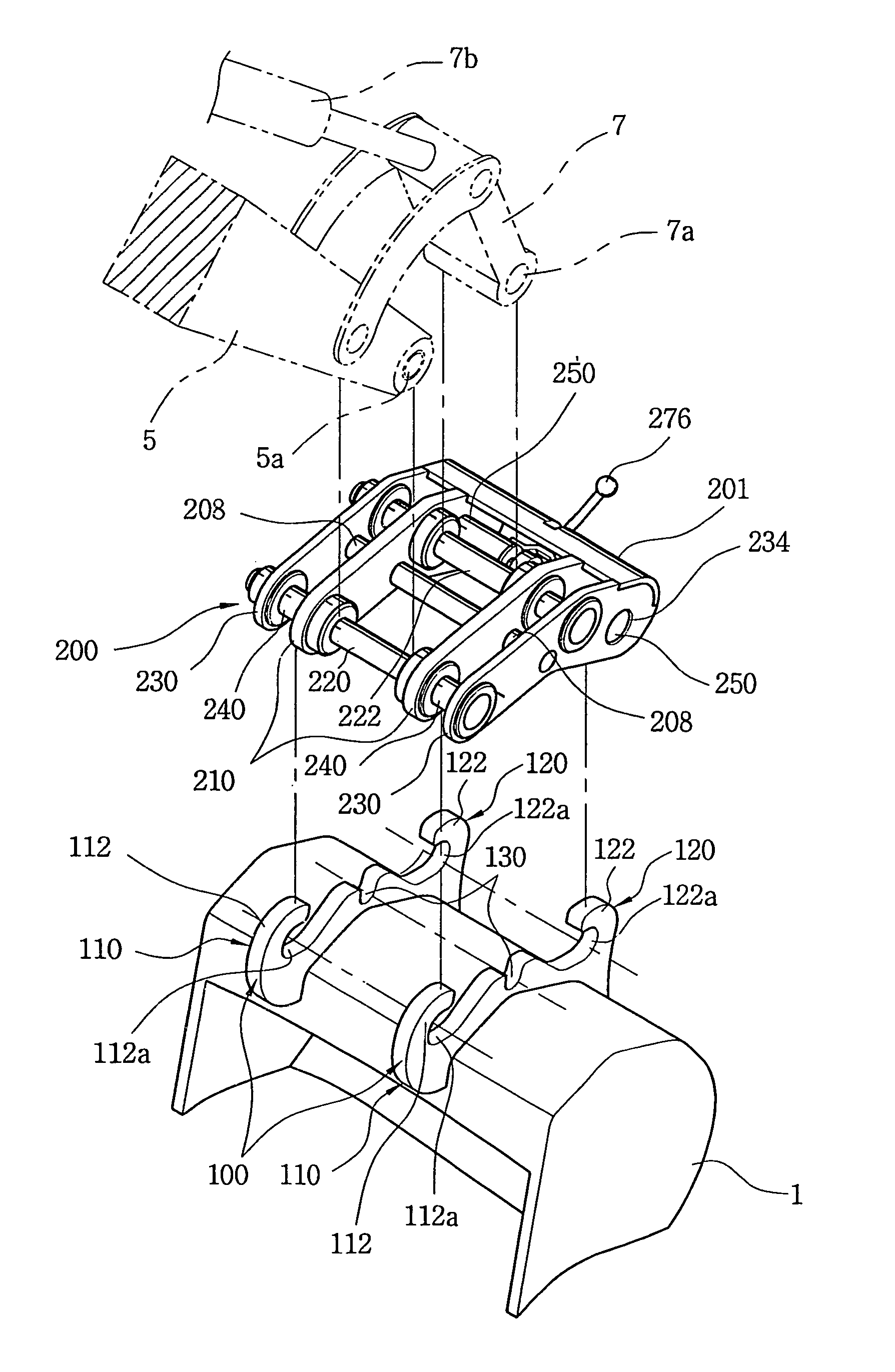
[0033]Referring first to FIG. 3, it can be understood that the attachment coupling device of the present invention comprises a pair of mounting brackets 100 affixed to a bucket 1, and a coupler 200 secured to an arm 5 of an excavator.

[0034]Each of the mounting brackets 100 has first and second coupling portions 110, 120 which are spaced apart from each other, fixedly placed side by side on a top surface of the bucket 1 and aligned on an identical vertical plane. Each of the first and second coupling portions 110, 120 includes first and second hooks 112, 122. The first and second hooks 112, 122 are constructed to face each other at opposite sides of each of the mounting brackets 100, and have engagement recesses 112a, 122a that are open inwards in a mutually confronting relationship with each other. Fur...


PUM


Abstract

An attachment coupling device is designed to releasably connect a variety of attachments to an arm and a push link of heavy machinery such as hydraulic excavators. The attachment coupling device comprises a pair of mounting brackets fixedly secured to the attachment, each bracket having first and second hooks spaced apart with each other. Another major element of the coupling device is a coupler which includes, a fixed plate affixed to the arm and the push link, a pair of fixed coupling pins each protruding outwardly from the fixed plate for engagement with the first hook of each of the mounting brackets, a pair of movable coupling pins for movement between a retracted release position and an extended coupling position wherein the respective one of the movable pins comes into engagement with the second hook of each of the mounting brackets, and an actuator for causing movement of the movable coupling pins.

Description

TECHNICAL FIELD[0001]The present invention is generally directed to heavy machinery and, more specifically to an attachment coupling device for detachably connecting a variety of attachments to an arm of excavators.BACKGROUND ART[0002]Excavators for use in construction or engineering work sites are adapted to perform a variety of works, such as bucket-used ground excavation, building crush and steel rod cutting through the use of a crusher, breakdown of rocks and concrete by use of a breaker, and transportation of scrap steel and rocks by virtue of a grab. The attachments employed in the excavators are changed with another one, depending on the work situations.[0003]Such attachments are releasably mounted onto an arm of excavators so that they can be changed with other type of attachments with ease, if necessary. Referring to FIG. 1, in which a bucket is illustrated as an example of the attachments, it will be seen that the bucket 1 is provided with a pair of spaced-apart, parallel,...

Claims


Application Information

Patent Timeline
Patent Type & Authority Patents(United States)
IPC IPC(8): F16D1/00E02F3/40E02F3/36
CPCE02F3/3618E02F3/3663Y10S37/903Y10T403/598Y10T403/59Y10T403/591Y10T403/595Y10T403/593
Inventor LIM, JONG HYUKLEE, SUNG CHAN
Owner HANWOO TNC CORP
Why Eureka
Try Eureka