Alignment tool

a technology of alignment tool and tool body, which is applied in the field of tools to achieve the effects of quick and convenient connection of alignment tool, high resistance, and quick and firm connection of two components

Active Publication Date: 2019-07-30
TSO PROD LLC
View PDF13 Cites 5 Cited by
  • Summary
  • Abstract
  • Description
  • Claims
  • Application Information

AI Technical Summary

Benefits of technology

[0007]The purpose and advantages of the present invention will be set forth in and apparent from the description and drawings that follow, as well as will be learned by practice of the claimed subject matter. It is the object of this invention to introduce an alignment tool and method of using the alignment tool that effectively provide a connection to a work component which is precise as well as simple, and resistant to unintended change during use.
[0013]As above noted, the example alignment tools and example methods of assembling an alignment tool to a work component of this disclosure provide several advantageous features. The example alignment tools and methods provide the ability to quickly and conveniently connect the alignment tool to a work component, without need to use a separate gage to check the accuracy of the alignment between the two components, or to use any tools. Additionally, the clamp assembly holds the two components together firmly and makes the connection highly resistant to unintended misalignment during handling of the connected components, which may be aided by a biasing element. A quick and firm connection of the two components is provided.

Problems solved by technology

However, unlike the prior art, the inventive alignment tools do not rely on traditional T-slot style connections as the principal means of alignment, due to the aforementioned disadvantages of such traditional connections.

Method used


Image

  • Alignment tool
  • Alignment tool
  • Alignment tool

Examples


Embodiment Construction

[0028]For the following defined terms, these definitions shall be applied, unless a different definition is given in the claims or elsewhere in this disclosure. As used in this disclosure and the claims, the singular forms “a”, “an”, and “the” include plural referents unless the content clearly dictates otherwise. As used in this disclosure and the claims, the term “or” is generally employed in its sense including “and / or” unless the content clearly dictates otherwise.

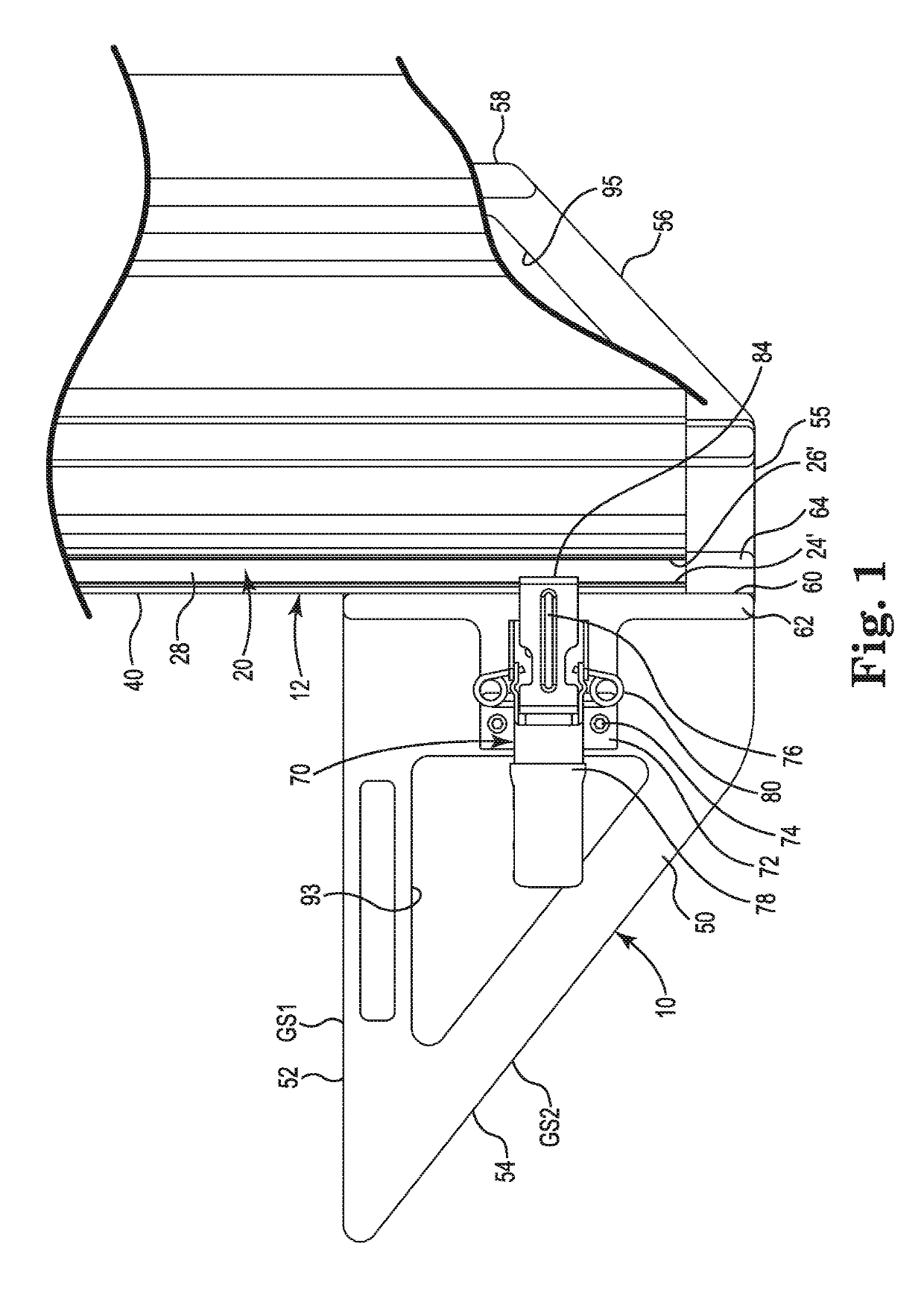
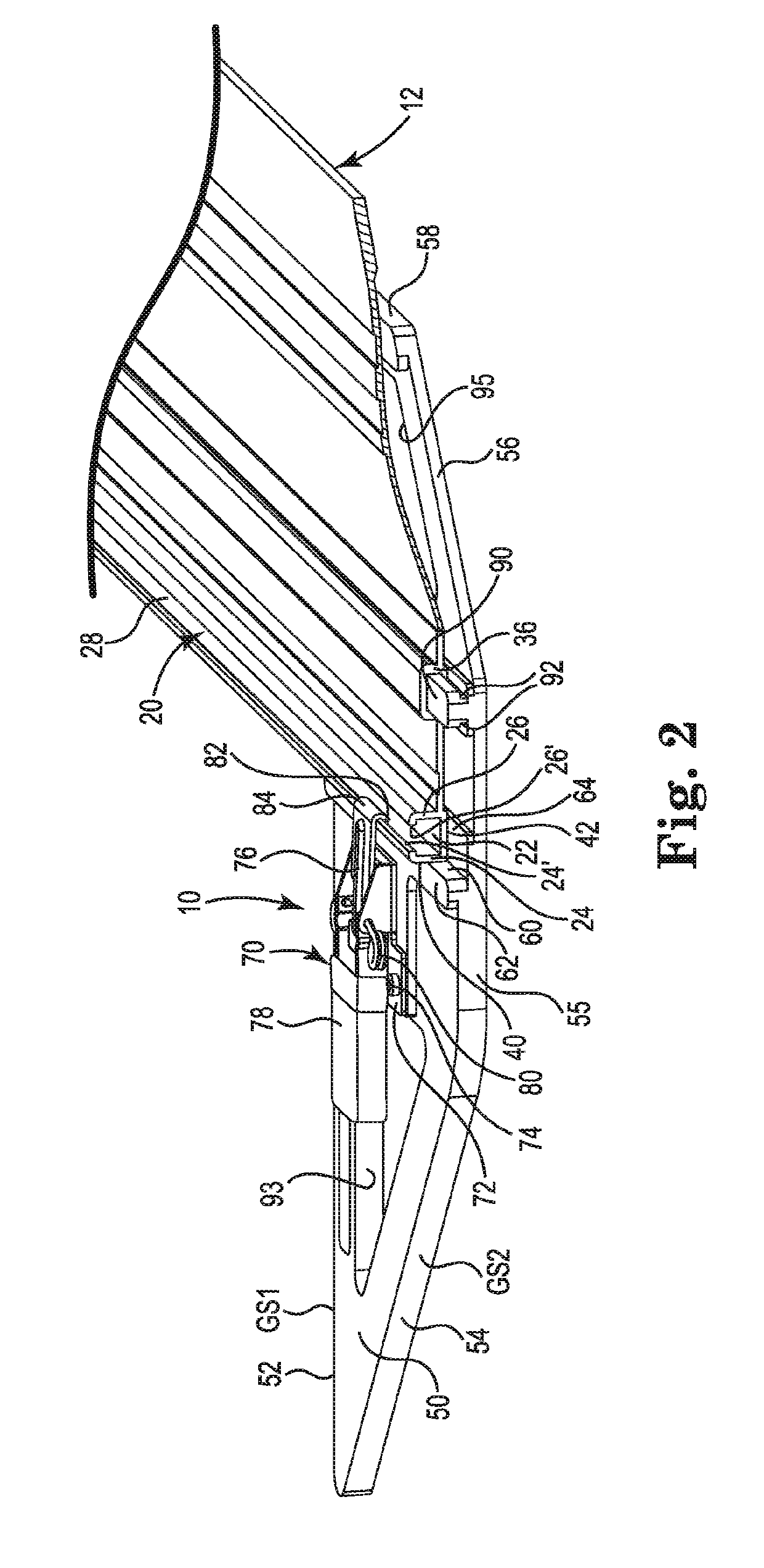
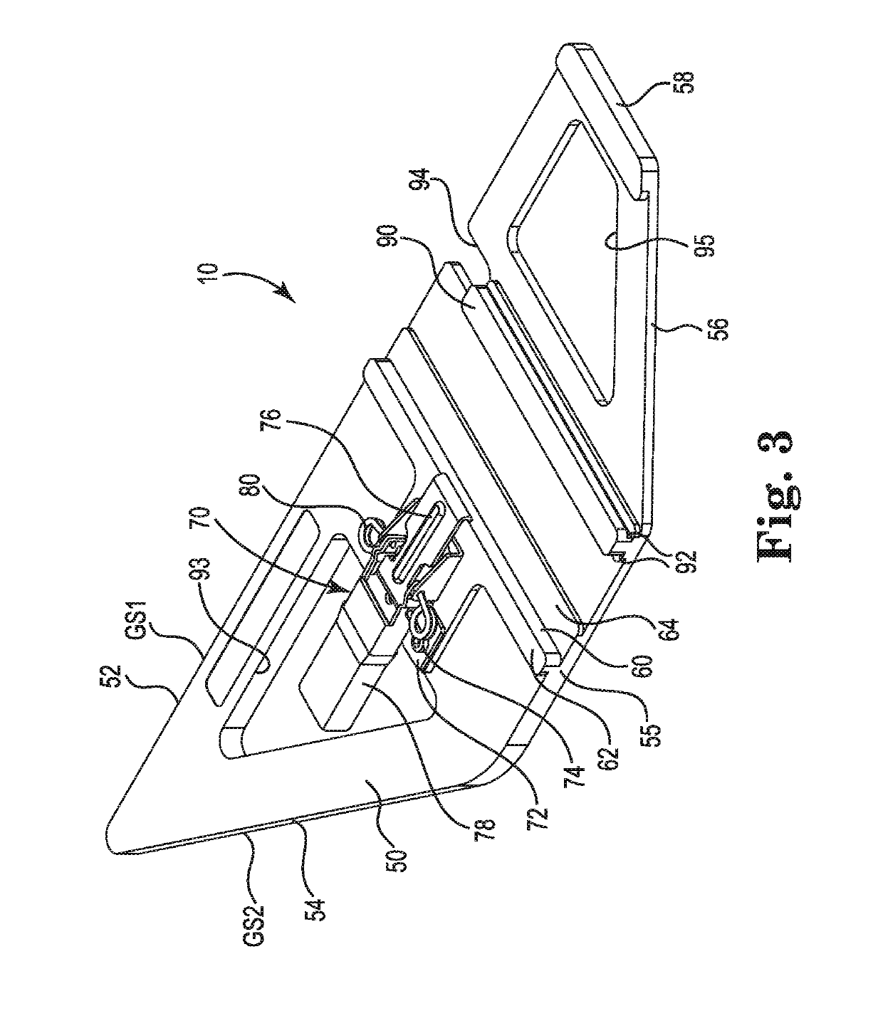
[0029]Referring generally to FIGS. 1-10, it will be appreciated that alignment tools of the present disclosure generally may be embodied within numerous configurations, and may be used in various ways to enhance the convenience of users. Indeed, while acknowledging that all of the example configurations of alignment tools need not be shown herein, examples are provided to better demonstrate that a variety of configurations and methods of use are contemplated.

[0030]Turning to a first example embodiment of an alignment t...


PUM

PropertyMeasurementUnit
forcesaaaaaaaaaa
torqueaaaaaaaaaa
timeaaaaaaaaaa

Abstract

An alignment tool for connection to a work component and for use in aligning the work component with a work piece, wherein the work component has at least a first reference surface that extends in a first direction. The alignment tool includes a body having at least a first reference surface that extends in the first direction and having at least one work piece guide surface that extends in a second direction that is perpendicular to the at least first reference surface, and a clamp assembly connected to the body and extending in the second direction past the at least first reference surface of the body, wherein when the alignment tool is to be connected to the work component, the clamp assembly is movable to engage the work component and to draw together and hold in abutting engagement the respective first reference surfaces of the alignment tool and work component.

Description

CROSS-REFERENCE TO RELATED APPLICATION[0001]This application claims the benefit of priority of U.S. Provisional Patent Application Ser. No. 62 / 356,758, filed Jun. 30, 2016 and PCT Application Serial No. PCT / US17 / 40056, filed Jun. 29, 2017, the disclosure of which is hereby incorporated by reference in its entirety.BACKGROUND OF THE INVENTIONField of the Invention[0002]The present invention generally relates to tools that provide temporary or longer term connection to a work component to establish a precision gage or guide, and more particularly a quick and accurate way to removably join an alignment tool to a work component by using complementary reference surfaces.Discussion of the Prior Art[0003]The alignment and connection of separate elements of tools, fixtures, and guide assemblies often relies on use of channels, such as in the form of T-shaped slots, commonly referred to as “T-slots”, in one or more of the components to be connected for temporary or longer term use. This has ...

Claims


Application Information

Patent Timeline
Patent Type & Authority Patents(United States)
IPC IPC(8): B23P11/00B23D59/00B23D47/02B27B9/04
CPCB27B9/04B23D59/00B23D47/02
Inventor FRIEDEBACH, ADOLF HANS
Owner TSO PROD LLC
Why Eureka
Try Eureka